Ring segment of gas turbine

a gas turbine and ring segment technology, applied in the field of ring segments, can solve the problems of gas turbines suffering undesirable driving power loss, easy to suffer high temperature oxidation, danger of damage, etc., and achieve the effects of preventing damage to the ring segment due to high temperature oxidation, and enhancing the fatigue strength of the ring segmen

Inactive Publication Date: 2006-04-25
MITSUBISHI HEAVY IND LTD
View PDF14 Cites 115 Cited by
  • Summary
  • Abstract
  • Description
  • Claims
  • Application Information

AI Technical Summary

Benefits of technology

[0040]In the ring segment of a gas turbine, since the ring segment is made from nickel alloy, not only is the fatigue strength of the ring segment enhanced, but also high temperature oxidation of the ring segment is impeded. Accordingly, damage to the ring segment due to high temperature oxidation is prevented, and the flow amount of working fluid which leaks to the outside, and the flow amount of air which leaks to the inside, are both reduced. Due to this, it is possible to prevent loss of driving power of the gas turbine.

Problems solved by technology

These heated up corner edge portions 26 reach high temperatures locally, and undesirably suffer deterioration due to the occurrence of high temperature oxidation.
Furthermore, even if the air is blown out at a suitable pressure, since the corner edge portions 26 are heated up by the high temperature gas which is flowing along the inner peripheral surface 24 and also by the high temperature gas which insinuates into the gaps e between adjacent ones of the individual units 8a, accordingly they can easily suffer high temperature oxidation, and there is a danger that they may be damaged.
Furthermore, if the air is no longer being sucked out at a suitable pressure, the high temperature gas may flow out to the outer peripheral side of the ring segment 8 via the gap e. If the high temperature gas or the air leaks in this manner, the gas turbine will suffer an undesirable loss of driving power, and its operational performance will be deteriorated.

Method used


Image

  • Ring segment of gas turbine
  • Ring segment of gas turbine
  • Ring segment of gas turbine

Examples


Embodiment Construction

[0052]In the following, the preferred embodiment of the ring segment of a gas turbine according to the present invention will be explained with reference to FIGS. 1 through 7. It should be understood that to elements which are the same as elements of the prior art described above with reference to FIGS. 8 through 11, the same reference symbols are affixed as in those figures, and the explanation thereof will be curtailed.

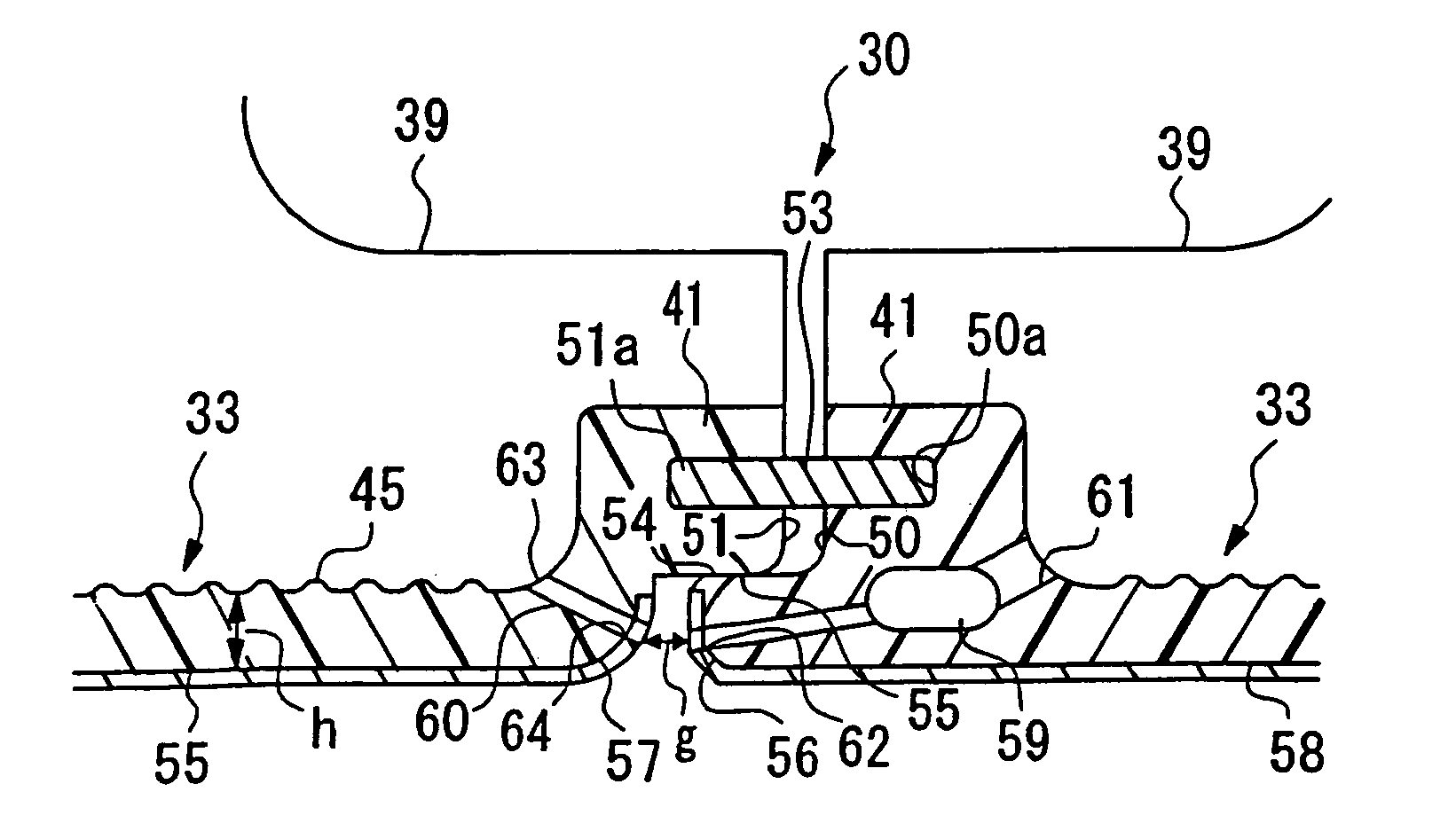
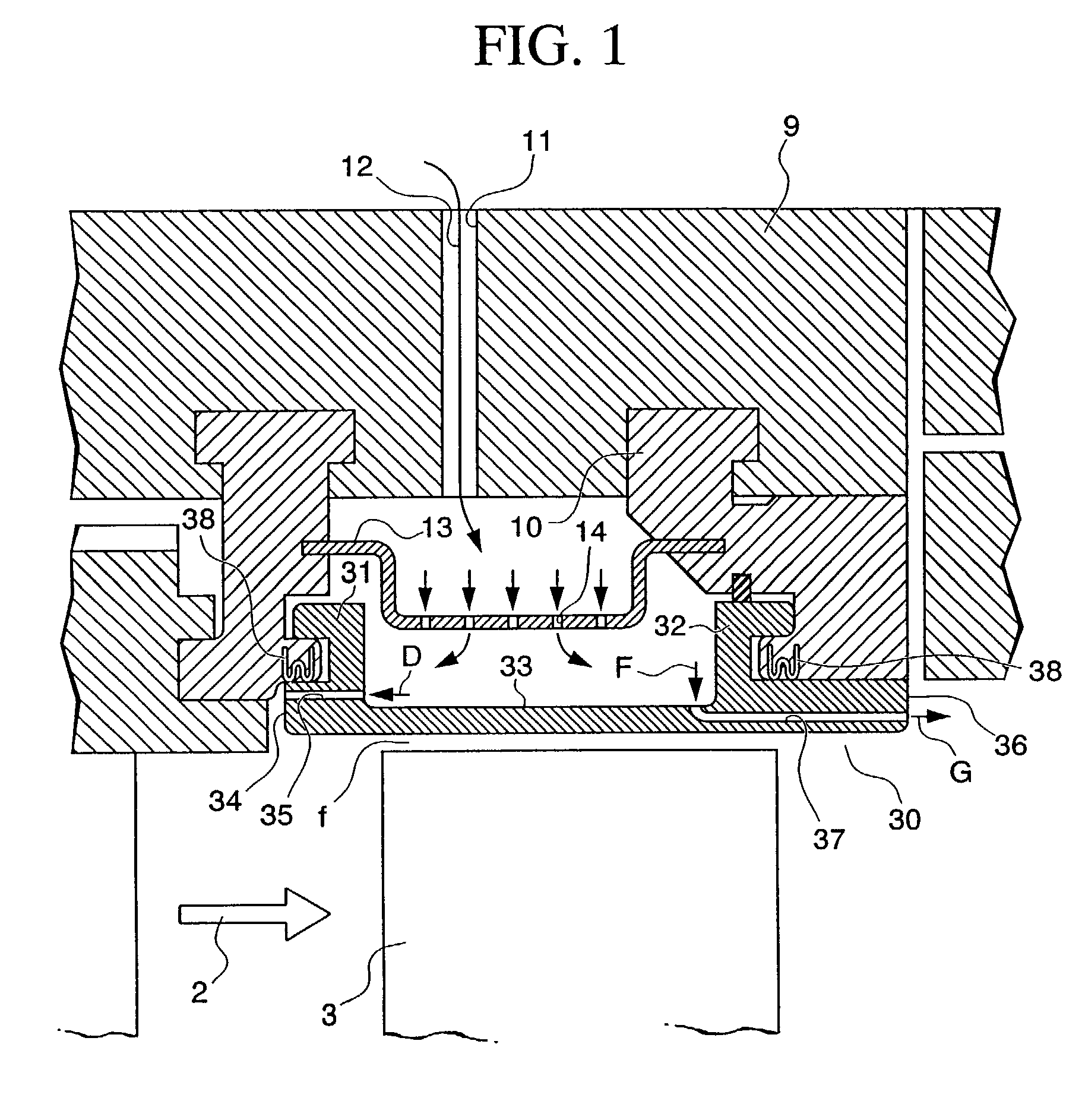
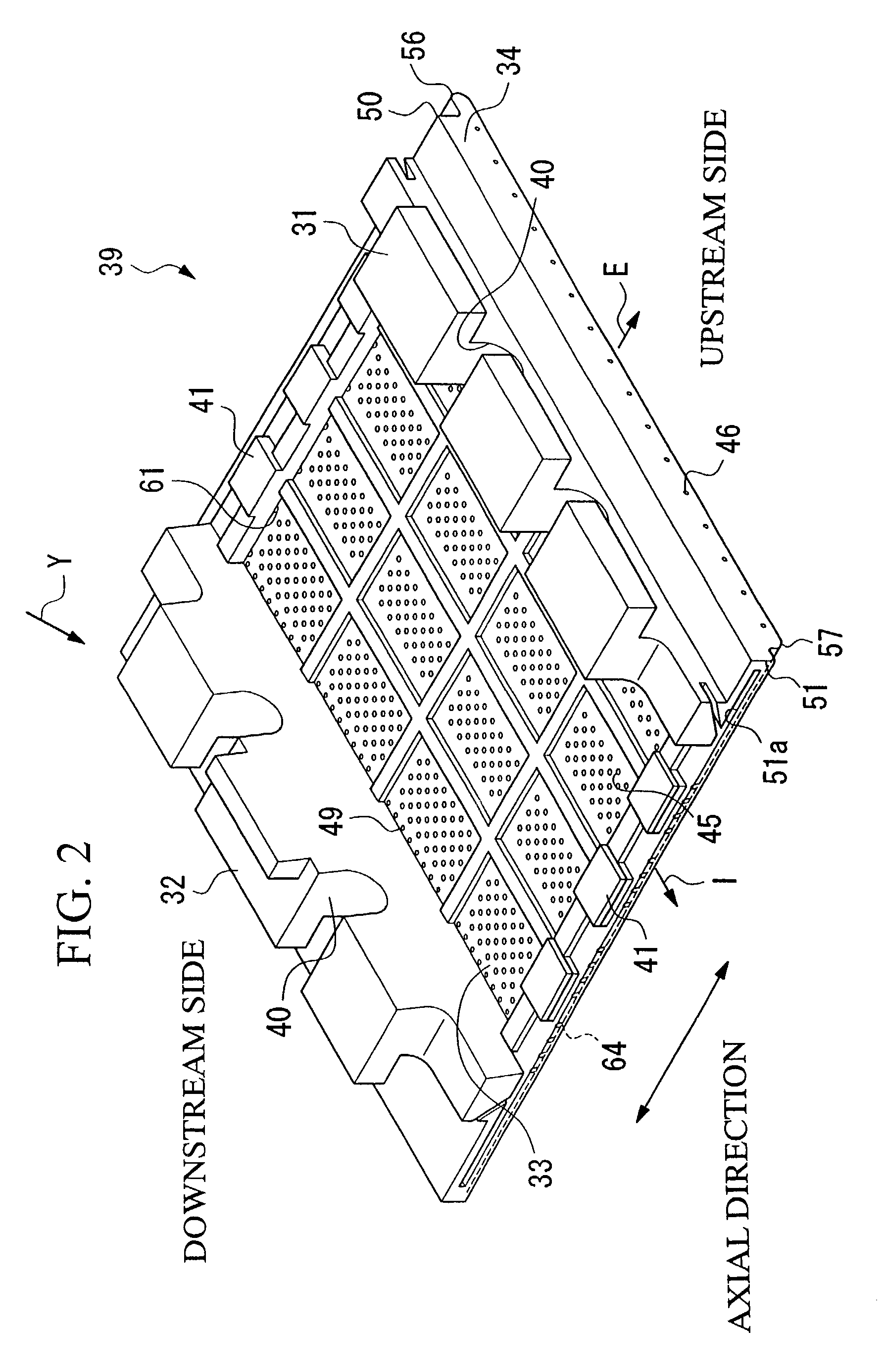
[0053]FIG. 1 is a cross sectional view of a ring segment 30 of a gas turbine according to the preferred embodiment of the present invention. This ring segment 30 is made from nickel alloy. The ring segment 30 is attached to isolating rings 10 by a flange 31 which is provided on the upstream side in the flow direction of high temperature gas and a flange 32 which is provided upon the downstream side. To the ring segment 30 there are provided first cooling conduits 35 which are pierced from the outer peripheral surface 33 at its upstream side to its end surface 34 at ...


PUM


Abstract

An object of the present invention is to provide a ring segment of a gas turbine in which the temperature is maintained low, damage due to high temperature oxidation is prevented, and high temperature deformation is prevented. In order to achieve the object, the present invention provides a ring segment of a gas turbine which comprises a blade ring, a main shaft and moving blades comprising a plurality of individual units which define an annular form by being arranged around the peripheral direction of the main shaft, and disposed so that its inner peripheral surface is maintained at a constant distance from the tips of the moving blades, wherein grooves which extend along the axial direction of the main shaft of the turbine are formed upon of the individual units so as mutually to confront one another; a seal plate which is inserted into each mutually confronting pair of the grooves so as to connect together the adjacent pair of individual units; and contact surfaces which are formed at positions more radially inward than the seal plates, which extend in the axial direction and the peripheral direction and which mutually contact one another.

Description

BACKGROUND OF THE INVENTION[0001]1. Field of the Invention[0002]The present invention relates to a ring segment of annular form which is disposed around the outer periphery of the moving blades in a gas turbine.[0003]2. Description of the Related Art[0004]FIG. 8 shows a turbine 1 in section, which is a gas turbine. In this turbine 1, gas at high temperature which has been generated by a combustors (not shown in the figures) is supplied in the direction shown by the arrow 2 and blows against moving blades 3 and 4 so as to rotate the moving blades 3 and 4, and the heat energy in the high temperature gas is converted in this manner to mechanical rotational energy of the moving blades 3 and 4, so as to generate drive power.[0005]The moving blades 3 and 4 are fixed to a mounting platform 5 which is fitted around a main shaft (not shown in the figure). A plurality of these moving blades 3 and 4 are provided around the main shaft, spaced apart along its peripheral direction. They receive t...

Claims


Application Information

Patent Timeline
Patent Type & Authority Patents(United States)
IPC IPC(8): F01D25/08F01D9/04F01D9/02F01D11/00F01D11/08F01D25/12F01D25/24F02C7/18
CPCF01D11/005F01D11/08F01D25/246F01D25/12F05D2260/201F05D2240/55
Inventor TOMITA, YASUOKIISUMI, OSAMUINOUE, SHINICHISOECHTING, FRIEDRICHLAURELLO, VINCENTMATSUOKA, HIROSHIGE
Owner MITSUBISHI HEAVY IND LTD
Why Eureka
Try Eureka