Helical coil, Magnetic core antenna

a technology of magnetic core and helical coil, which is applied in the direction of loop antennas, radiating element structural forms, electrical devices, etc., can solve the problems of considerable restrictions on ohmic losses in antennas, and achieve the effects of low ohmic equivalent resistance, considerable transmission power, and low gain

Inactive Publication Date: 2006-04-25
ANCOM
View PDF11 Cites 4 Cited by
  • Summary
  • Abstract
  • Description
  • Claims
  • Application Information

AI Technical Summary

Benefits of technology

[0013]Antennae according to the invention distinguish themselves by the basic configuration exhibiting little gain; in terms of radiation pattern they are approximately isotopic, which means that they are not very direction-oriented. Low ohmic equivalent resistance allows an antenna containing a ferrite rod to be used as a transmitting antenna, also at considerable transmission power. Further, it is a great advantage that the antenna may readily be tuned without the use of special tuning circuits. Tests that have been carried out indicate that the antenna is principally a magnetic antenna. Compared with other magnetic transmitting antennae, the antenna according to the invention has a considerably smaller physical size and weight.

Problems solved by technology

The ohmic losses in an antenna places considerable restrictions e.g. on the use of ferrite in transmitting antennae, as overheating changes the magnetic property of the ferrite.

Method used


Image

  • Helical coil, Magnetic core antenna
  • Helical coil, Magnetic core antenna
  • Helical coil, Magnetic core antenna

Examples


Embodiment Construction

[0008]The object of the invention is to remedy the negative aspects of prior art.

[0009]The object is achieved in accordance with the invention by the characteristics stated in the undermentioned description and in the appended claims.

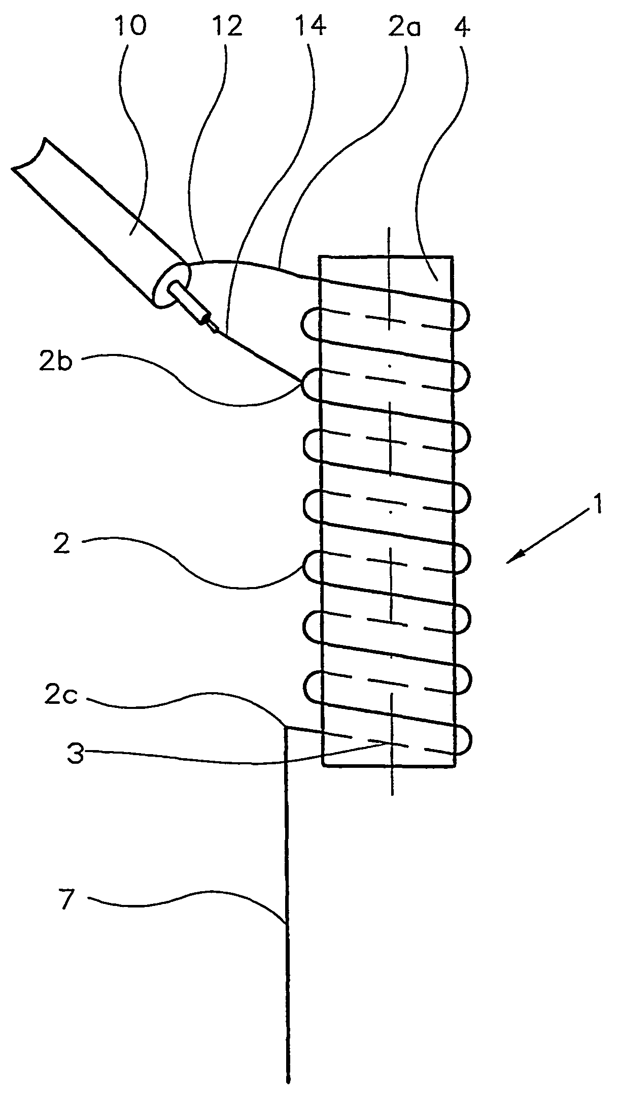
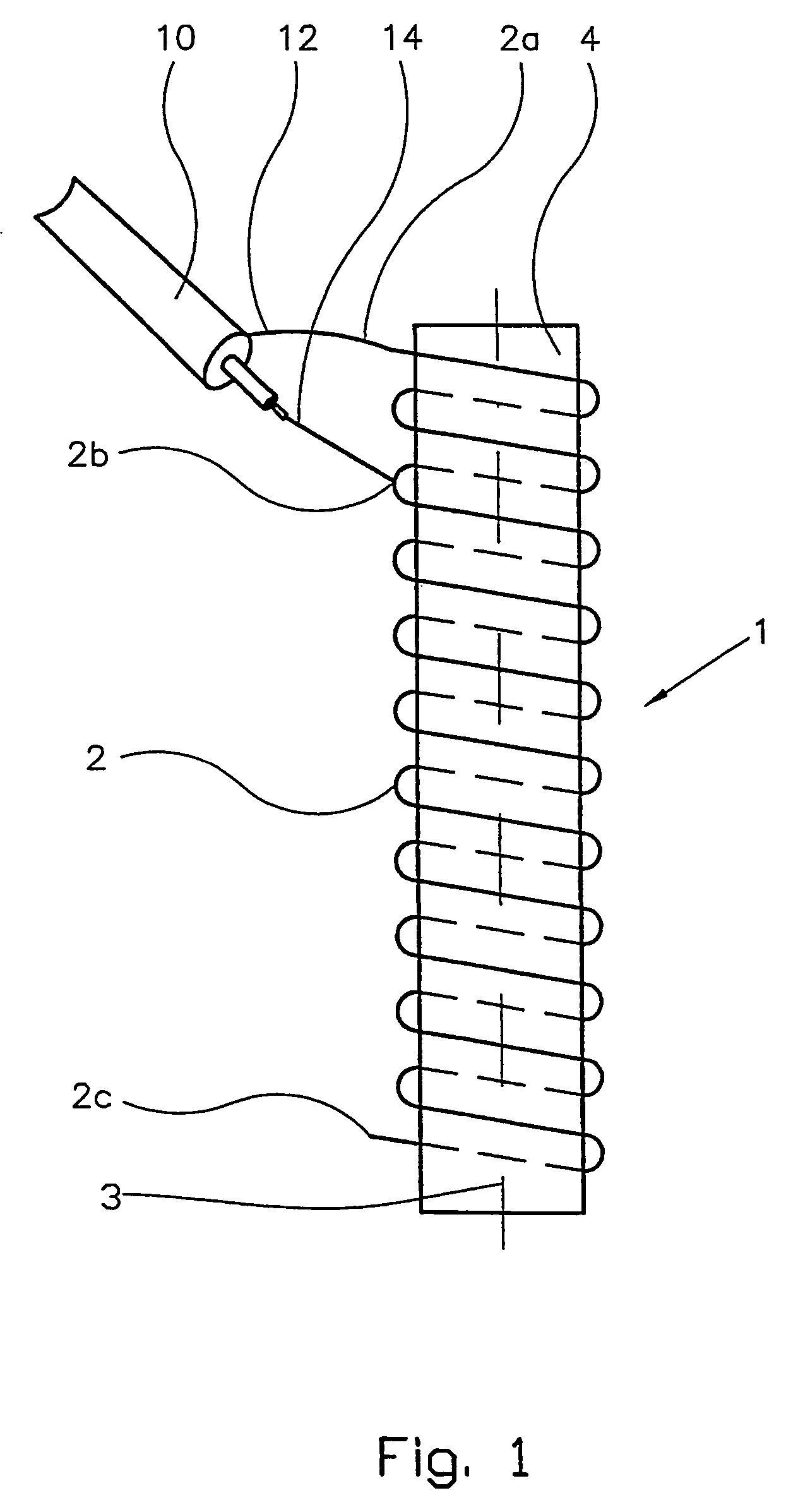
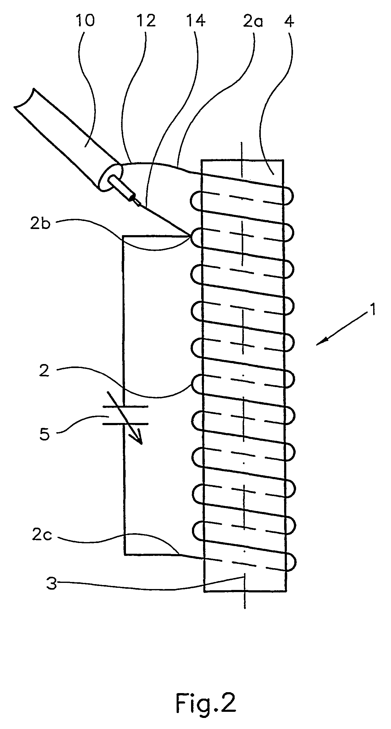
[0010]In its basic configuration, the antenna comprises a coil in which one conductor of a connecting cable is connected to one end portion of the coil, and where the other conductor of the connecting cable is connected to the coil at a point between the two end portions of the coil. The number of coil windings between the two connection points must be adapted to the frequency range in which the antenna is to operate. The part of the coil which is located between the connection points constitutes the feeder part of the antenna. The remainder of the windings of the antenna, the resonant part, which forms an extension of the feeder windings, requires a number of windings sufficient to make the antenna resonant without the use of a capacitor or other tunin...


PUM


Abstract

A device by an antenna (1) where the coil conductor (2) of the antenna is wound around a ferrite rod/tube (4), and where one conductor (12) of a connecting cable (10) is electrically coupled to one end portion (2a) of the coil conductor (2) of the antenna (1), and the other conductor (14) of the connecting cable (10) is electrically coupled to a connection point (2b), the connection point (2b) being located on the coil conductor (2), between the two end portions (2a) and (2c) of the coil conductor.

Description

CROSS REFERENCE TO RELATED APPLICATION[0001]The present application is the U.S. national stage application of International Application PCT / NO01 / 00441, filed Nov. 5, 2001, which international application was published on Jun. 6, 2002 as International Publication WO 02 / 45210. The International Application claims priority of Norwegian Patent Application 20005604, filed Nov. 6, 2000.SUMMARY OF THE INVENTION[0002]This invention regards a transmitting and receiving antenna that upon connection to a suitable device generates and / or is sensitive mainly to the magnetic part of an electromagnetic field.[0003]Antenna theory often bases itself on a single dipole antenna, which in literature is termed a “Hertzian dipole” antenna. This type of antenna is very short relative to the wavelength of the electromagnetic field. The electromagnetic radiation of the dipole antenna is largely dependent on the direction in question, relative to the principal axis of the antenna. Thus the dipole antenna is ...

Claims


Application Information

Patent Timeline
Patent Type & Authority Patents(United States)
IPC IPC(8): H01Q7/08H01Q1/36
CPCH01Q7/08
Inventor KARLSEN, HELGE IDAR
Owner ANCOM
Why Eureka
Try Eureka