Dispersion management for long-haul high-speed optical networks

a high-speed optical network and long-haul technology, applied in the field of optical transport networks, can solve the problems of adversely affecting the industry's ability to meet demand, single-mode fiber is more difficult to splice and connect light into, and chromatic dispersion and fiber nonlinearities present significant obstacles to achieving higher system data rates and longer transmission distances (reach), so as to improve performance and improve propagation, the effect of increasing the demand for more services

Inactive Publication Date: 2006-04-25
RPX CLEARINGHOUSE
View PDF31 Cites 8 Cited by
  • Summary
  • Abstract
  • Description
  • Claims
  • Application Information

AI Technical Summary

Benefits of technology

[0034]Still another aspect of the dispersion management solution according to the invention is to provide ways of managing the end-to-end dispersion of a communication path, using the DM cable and taking into consideration all active and passive network elements in the respective path. Consideration is also given to the evolution of the path from simple to complex, as the user demand on more services grow.
[0035]The dispersion management solution according to the invention provides improved performance over the currently available solutions, allowing communication at 80 Gbps rates and higher. The communication system as a whole presents improved propagation, and lower overall amplifier noise figure. As well, the dispersion management solution of the invention allows for increased transmission reach, and results in increased spectral efficiency.
[0036]In addition, the solution offered by the present invention offers a less expensive end-to-end transmission path, in that it reduces / eliminates the DCM's, providing a simpler configuration for the optical line amplifier, with a slight increase in the cable plant cost.

Problems solved by technology

In communication systems which utilize optical fiber as a transmission medium, chromatic dispersion and fiber nonlinearities present significant obstacles to achieving higher system data rates and longer transmission distances (reach).
On the other hand, the single mode fiber is more difficult to splice and to connect light into it, due to the smaller diameter of the core.
However, the production rates of NZDSF are slower than those of SMF, adversely affecting the industry ability to meet demand.
Specifically, complete cancellation of dispersion in all channels at the end of the system is not easily accomplished, primarily because the dispersion slope in the compensating fibers typically cannot meet the two requirements of being high in magnitude and negative in sign.
Thus, fibers with high negative dispersion and high negative slope are difficult to manufacture and therefore expensive.
Small variations in fiber designs having these properties typically lead to large changes of other properties of the fiber, and hence such designs are typically not reliably manufacturable.
Also, there is a large installed base of SMF fiber, and even if SCF were easier to manufacture, replacing of the existing outside cable plant would be very costly.
As discussed above, dispersion compensation results in adding attenuation to the signal, which limits the possible spacing of the terminals.
On the other hand, EDFA's are expensive units and so the number and types of units required to implement a given data connection is an important design parameter for an optical network.
Furthermore, the EDFA gain is not perfectly flat for all wavelengths, the precise wavelengths to use being a function of the gain variations of the different available pumps.
Gain tilt is a significant issue when designing DWDM systems.

Method used


Image

  • Dispersion management for long-haul high-speed optical networks
  • Dispersion management for long-haul high-speed optical networks
  • Dispersion management for long-haul high-speed optical networks

Examples


Embodiment Construction

[0050]The aim of undertaking dispersion management in the outside plant is to emulate the attributes of a theoretical “perfect” fiber, which would have ideally low attenuation, near zero dispersion slope, finite local dispersion with defined near zero average value, low non-linearity medium in high power region and high Raman Figure of merit in low power region (to enable low noise Raman preamplification), and good cable performance.

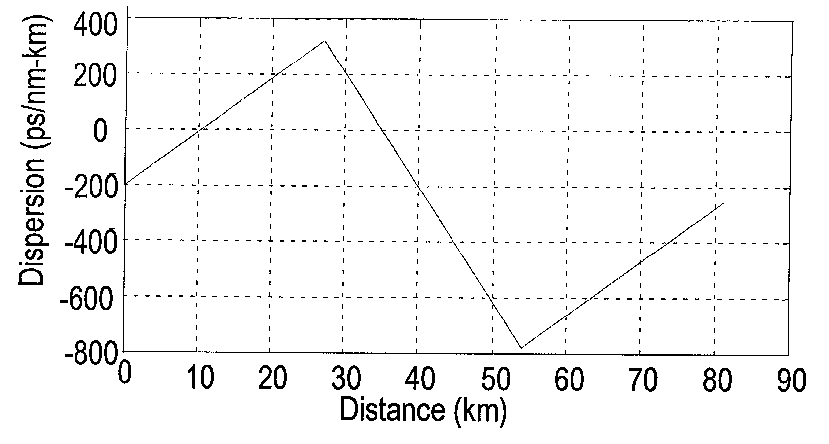
[0051]It is possible to construct dispersion managed systems by incorporating lengths of fiber with opposite dispersion and dispersion slope into the cable, and coupling (e.g., splicing) the fibers in correct sequences.

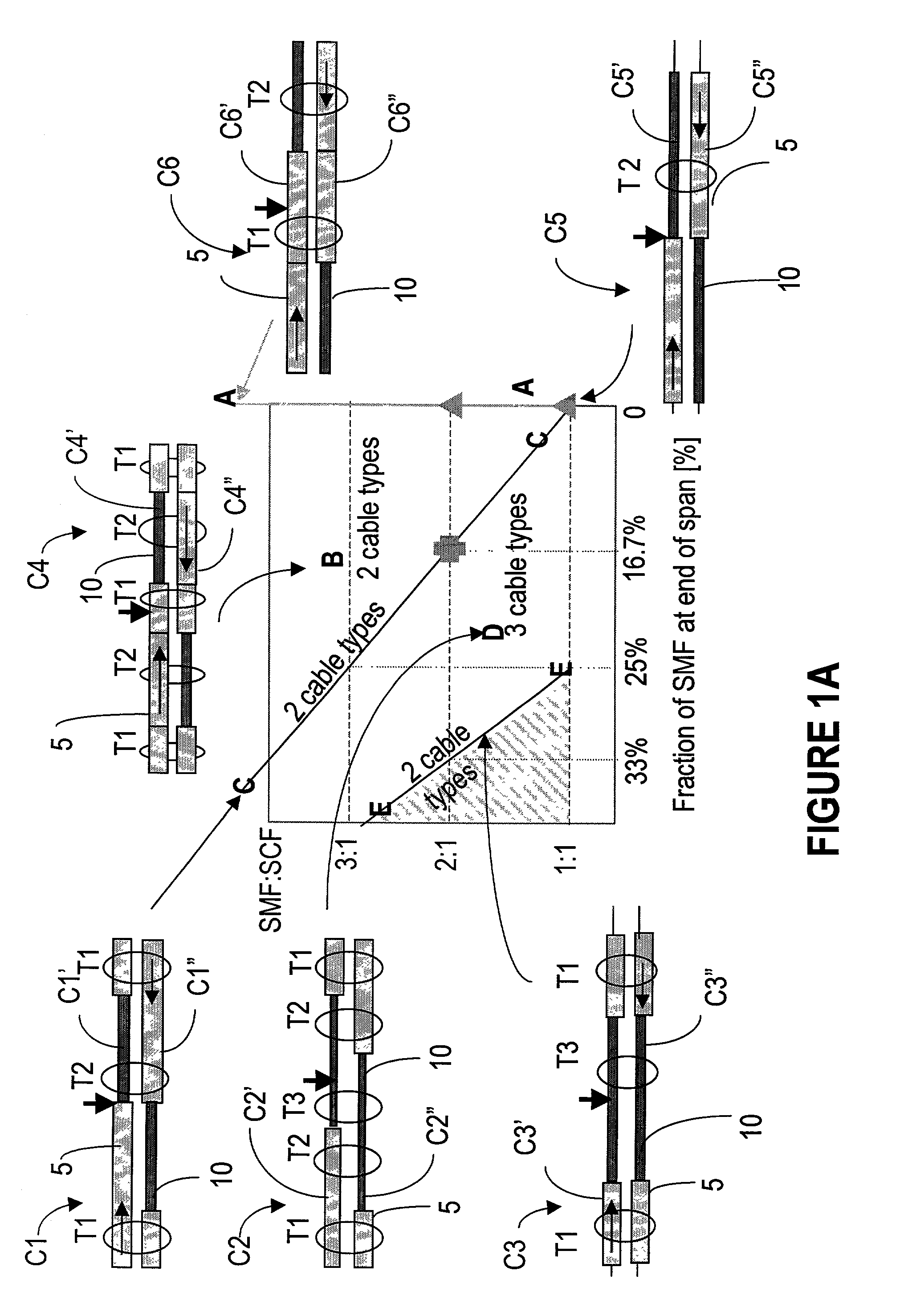
[0052]FIG. 1 illustrates various configurations C1–C6 for dispersion managed cables according to the invention, for a bidirectional communication system. Each variant comprises two mirror cables denoted with C1′, C1″; . . . ; C6′, C6″ running along each other, each for a direction of transmission. In this figure, fiber 5 is SMF with negati...


PUM


Abstract

The dispersion managed solution for long haul, high speed D/WDM systems according to the invention operates on three closely related aspects of the communication system. One is provision of a new type of dispersion managed (DM) optical cable with improved dispersion performance over the existing unidirectional and bidirectional cables. Another aspect considered is providing a communication path implemented over DM cable with distributed Raman amplification, to obtain a transmission reach of 2000 km and more, without regeneration. Still another aspect of the dispersion management solution according to the invention is to provide ways of managing the end-to-end dispersion of a communication path, using the DM cable and taking into consideration all active and passive network elements in the respective path. Consideration is also given to the evolution of the path from simple to complex, as the user demand on more services grow.

Description

BACKGROUND OF THE INVENTION[0001]1. Field of the Invention[0002]The invention is directed to optical transport networks and in particular to dispersion management for long-haul, high-speed optical networks.[0003]2. Background Art[0004]In communication systems which utilize optical fiber as a transmission medium, chromatic dispersion and fiber nonlinearities present significant obstacles to achieving higher system data rates and longer transmission distances (reach). “Chromatic dispersion” is the linear, power-independent dependence of light velocity on wavelength. The dispersion is measured in pulse spread in pico seconds, for a certain wavelength in nanometers, over a distance in kilometers (ps / nm / km).[0005]Typically, the diameter of the optical cable is about 125 microns but the core itself comes in to two different sizes, depending on the application the fiber is intended for. The fiber with a core diameter of 50 microns is known as multimode fiber, and the fiber with a core diam...

Claims


Application Information

Patent Timeline
Patent Type & Authority Patents(United States)
IPC IPC(8): H04B10/12H04B10/2507H01S3/067H01S3/30H04B10/2513H04B10/291
CPCH04B10/2916H04B10/25253H01S3/302H01S3/06754
Inventor MCNICOL, JOHN D.
Owner RPX CLEARINGHOUSE
Why Eureka
Try Eureka