Label switch network system

Inactive Publication Date: 2006-04-25
FUJITSU LTD
View PDF13 Cites 53 Cited by
  • Summary
  • Abstract
  • Description
  • Claims
  • Application Information

AI Technical Summary

Benefits of technology

[0029]In the conventional method, the status information was exchanged hop by hop among the adjacent nodes in the whole network and the process time was required in proportion to the number of hops among the nodes until the status information reached the whole network. Since in the present invention, all that the nodes have to do is to notify the policy server of the status, it is made unnecessary to exchange information hop by hop and process time is reduced.
[0030]Since the policy server executes all the processing of calculating appropriate L2 paths in reference to the status information and notifies nodes of the obtained result, it is unnecessary for each node to have the function of calculating the L2 paths and possible to constitute nodes at a low cost.
[0031]Also, the present invention makes it possible for a policy server to set up paths in respect of the traffic load sharing service so as not to make any imbalance in the network utilization.
[0032]Further, according to the present invention, through the introduction of redundant links, the present invention makes it possible to switch paths quickly when a failure arises. Namely, if the i

Problems solved by technology

In addition, the redundant link service cannot switch paths quickly when a failure arises in a working path, unless spare paths were set in the MPLS networks beforehand.
However the secured resources (including bandwidth for spare paths) cannot be utilized in normal use, thus lowering the resour

Method used


Image

  • Label switch network system
  • Label switch network system
  • Label switch network system

Examples


Embodiment Construction

[0048]Embodiments of the present invention will be explained with reference to the drawings.

[0049]Basic Configuration of Label Switch Network System

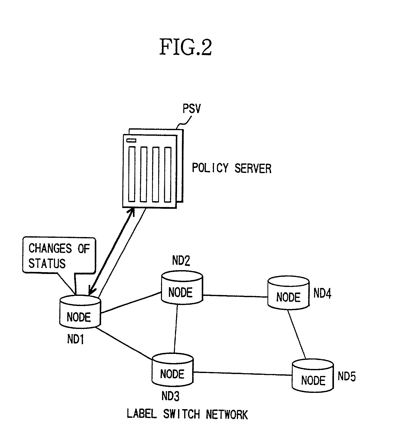
[0050]Referring to FIG. 2 that shows a basic configuration of the label switch network system according to one embodiment of the present invention, the label switch network system (a label network) is formed of a policy server PSV, and a plurality of nodes ND1, ND2 to ND5.

[0051]A policy server PSV is connected to a node ND1 disposed at the ingress of the label switch network by a physical line (a physical link). ND1 disposed at the ingress of the network and ND5 disposed at the egress of the network are connected by way of the intermediate (core) nodes, ND2, ND3 and ND4, and a physical line (physical link). The ingress node ND1 and the egress node ND5 are connected to other IP networks (illustration omitted), respectively.

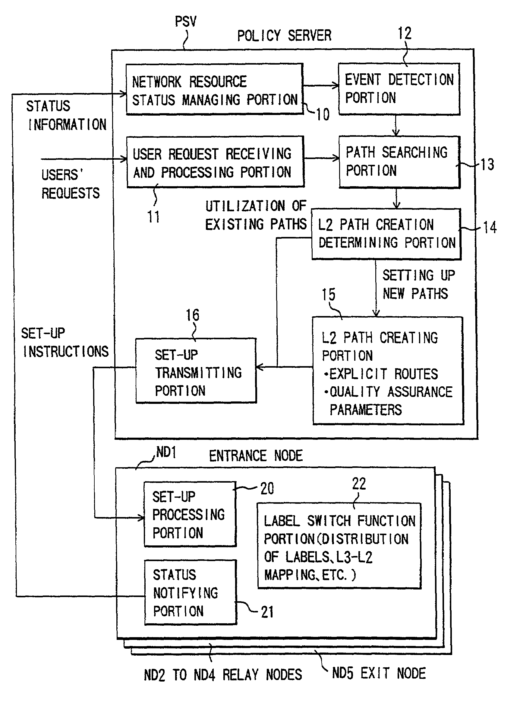
[0052]The policy server PSV determines operations of the nodes from ND1 to ND5, based on user information, policy (ma...


PUM


Abstract

The present invention relates to label switch networks and allows for reducing the processing cost and processing time required at each node when various services are performed with respect to traffic engineering in the label switch networks including a multi-protocol label switching (MPLS) network. In a label switch network system a first node that is disposed at the ingress of the label switch network transfers IP packets corresponding to IP flows based on labels, and that selects and sets up layer 2 paths for transferring the IP packets with reference to header or payload information of the IP packets. A plurality of second nodes may be disposed at intermediate points of the network and they set up the layer 2 paths from the ingress to the egress of the network following the specified routes and a third node is disposed at the egress of the network. A policy server instructs the first node to set up the layer 2 paths in compliance with policy control protocols when a user makes a request or a status change in the network arise, and intensively controls the first node, the second nodes and the third node.

Description

BACKGROUND OF THE INVENTION[0001]This invention relates to a label switch network system or a policy server and particularly a label switch network system that realizes traffic engineering by intensively controlling various flows in the label switch network or a policy server used in the label switch network system.[0002]In recent years, research and development on PBN (Policy Based Networking) and its application have been promoted with the aim of making IP (Internet Protocol) networks more sophisticated and simplifying its management and administration (Y. Nomura, et al., “Policy Based Networking Architecture for Enterprise Networks”, ICC' 99, 1999).[0003]Also, the MPLS (Multi Protocol Label Switching) technique has been attracting attention. The technique has introduced a new concept, “a label”, for transferring IP packets and can perform IP level (layer 3: L3) routing by a switching process in lower layers (layer 2:L2) such as ATM (Asynchronous Transfer Mode), frame intermediate...

Claims


Application Information

Patent Timeline
IPC IPC(8): H04L12/28H04L12/56H04L45/42H04L45/50
CPCH04L45/50H04L45/502H04L49/602H04L49/3009H04L49/25
Inventor NOMURA, YUJICHUGO, AKIRA
Owner FUJITSU LTD
Why Eureka
Try Eureka