Data communication apparatus
- Summary
- Abstract
- Description
- Claims
- Application Information
AI Technical Summary
Benefits of technology
Problems solved by technology
Method used
Image
Examples
first operation example
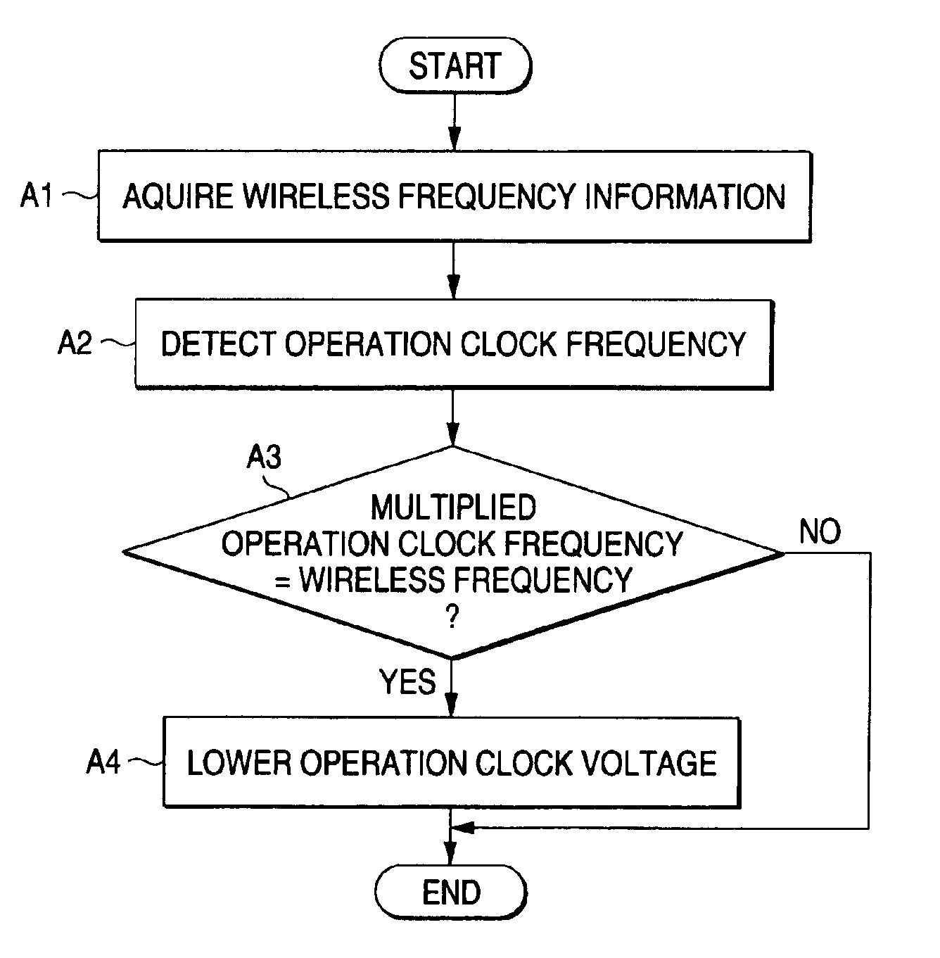
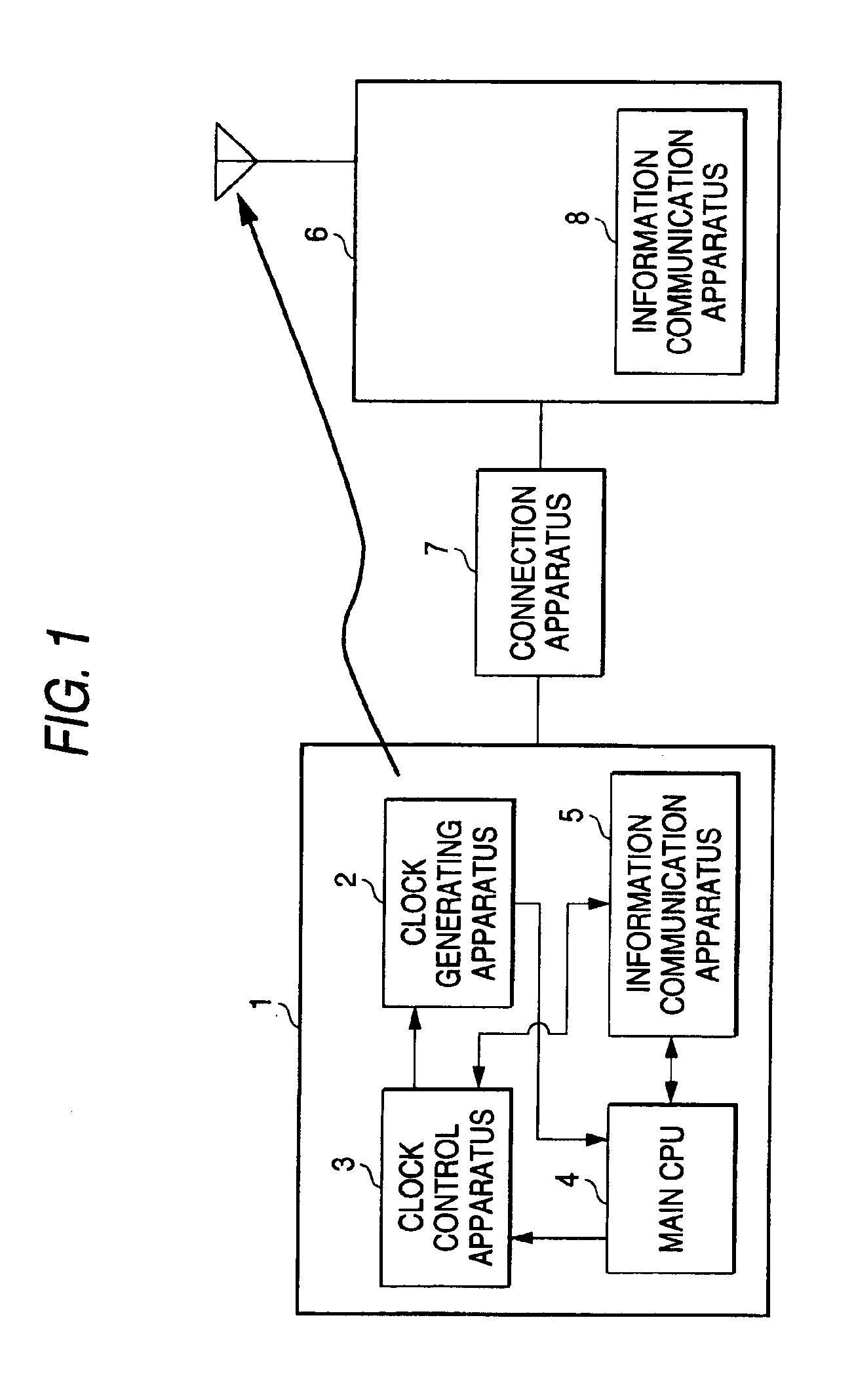
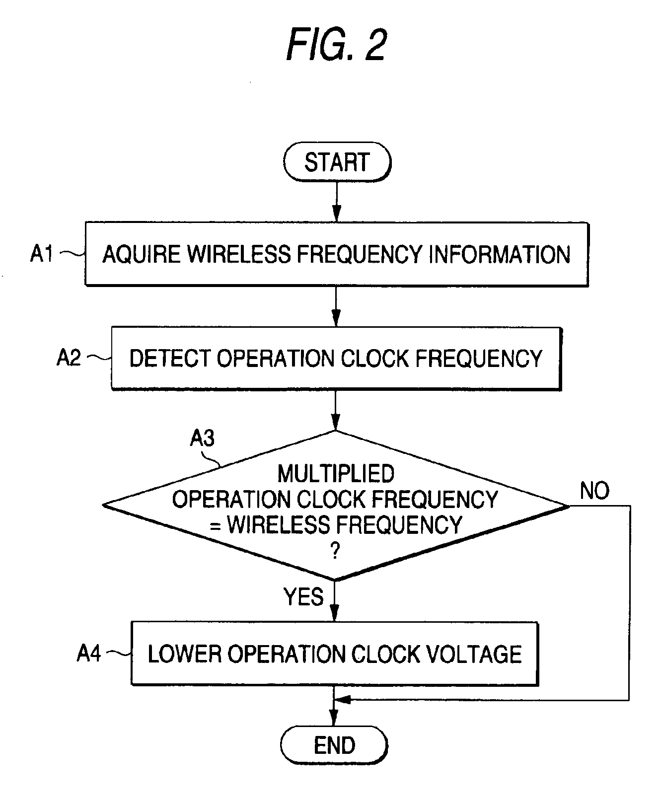
[0034]FIG. 2 is a flow chart for describing a first operation example of the clock control apparatus 3. First, the clock control apparatus 3 receives wireless frequency information of the wireless communication apparatus 6 from the information communication apparatus 5 (step A1). Next, the clock control apparatus 3 detects an operation clock frequency of the main CPU 4, namely a frequency of an operation clock supplied by the clock generating apparatus 2 to the main CPU 4 (step A2). The clock control apparatus 3 judges as to whether or not the multiplied operation clock frequency coincides with the wireless frequency. When the multiplied operation clock frequency coincides with the wireless frequency (“YES” at step A3), the clock control apparatus 3 lowers the voltage of the operation clock of the main CPU 4 to a minimum voltage value at which the operation of the main CPU 4 is guaranteed (step A4). To the contrary, when the multiplied operation frequency does not coincide with the ...
second operation example
[0035]FIG. 3 is a flow chart for explaining a second operation example of the clock control apparatus 3. It should be understood that steps B1 to B3 defined in this flow chart are identical to the steps A1 to A3 defined in the flow chart of FIG. 2, respectively. In this second operation example, in such a case that the multiplied operation clock frequency of the main CPU 4 coincides with the wireless frequency (“YES” at step B3), the clock control apparatus 3 shifts the frequency of the operation clock of the main CPU 4 to either a minimum frequency or a maximum frequency at which the operation of the main CPU 4 is guaranteed (step B4). When the operation clock frequency does not coincide with the wireless frequency, the clock control apparatus 3 does not execute the clock control operation, but accomplishes a series of this clock control operation.
third operation example
[0036]FIG. 4 is a flow chart for explaining a third operation example of the clock control apparatus 3. It should be understood that steps C1 to C3 defined in this flow chart are identical to the steps A1 to A3 defined in the flow chart of FIG. 2, respectively. In this third operation example, in such a case that the multiplied operation clock frequency of the main CPU 4 coincides with the wireless frequency (“YES” at step C3), the clock control apparatus 3 frequency-modulates the operation clock of the main CPU 4 so that the modulation degree does not exceed a frequency range at which the operation of the main CPU 4 is guaranteed (step C4). When the operation clock frequency does not coincide with the wireless frequency, the clock control apparatus 3 does not execute the clock control operation, but accomplishes a series of this clock control operation.
[0037]FIG. 5 indicates a frequency characteristic of a disturbance wave which is caused by the operation clock of the main CPU 4 in...
PUM
 Abstract
Description
Claims
Application Information
 - R&D
- Intellectual Property
- Life Sciences
- Materials
- Tech Scout
- Unparalleled Data Quality
- Higher Quality Content
- 60% Fewer Hallucinations
Browse by: Latest US Patents, China's latest patents, Technical Efficacy Thesaurus, Application Domain, Technology Topic, Popular Technical Reports.
© 2025 PatSnap. All rights reserved.Legal|Privacy policy|Modern Slavery Act Transparency Statement|Sitemap|About US| Contact US: help@patsnap.com


