Fieldbus relay arrangement and method for implementing such arrangement

a fieldbus relay and relay technology, applied in the field of fieldbus relay arrangement, can solve the problems of incompatibility of conventional relay devices with advanced technologies, lack of fieldbus relays, etc., and achieve the effect of simplifying the conversion of existing control systems to foundation® or profibus® fieldbus systems and advancing the level of control

Inactive Publication Date: 2006-04-25
SMAR RES CORP
View PDF13 Cites 57 Cited by
  • Summary
  • Abstract
  • Description
  • Claims
  • Application Information

AI Technical Summary

Benefits of technology

[0018]One of the advantages of the present invention is that the fieldbus relay can be considered as any other device on the FOUNDATION® or PROFIBUS® fieldbus, and may be operated with the same advanced level of control as any other fieldbus device. Fieldbus control strategies can thereby be configured with uniformity. Further, a conversion of existing control systems to FOUNDATION® or PROFIBUS® fieldbus systems can be simplified since a modification of existing output field elements is likely minimized. The use of the fieldbus relay arrangement according to the present invention makes the use of conventional discrete-controlled devices completely transparent at the fieldbus control configuration level.

Problems solved by technology

Many types of relays are unintelligent devices that merely conduct a load current when an input voltage is above or below a particular threshold input value.
However, these conventional relay devices are not compatible with the advanced technologies that have recently been developed for intelligent process automation and control.
However, no fieldbus relay exists which can be easily integrated into a fieldbus control scheme by executing fieldbus function blocks, receiving power from the fieldbus network, and performing various other functions which are generally performed by FOUNDATION® or PROFIBUS® fieldbus devices.

Method used


Image

  • Fieldbus relay arrangement and method for implementing such arrangement
  • Fieldbus relay arrangement and method for implementing such arrangement
  • Fieldbus relay arrangement and method for implementing such arrangement

Examples


Embodiment Construction

[0028]Preferred embodiments of the present invention and their advantages may be understood by referring to FIGS. 1–8, like numerals being used for like corresponding parts in the various drawings.

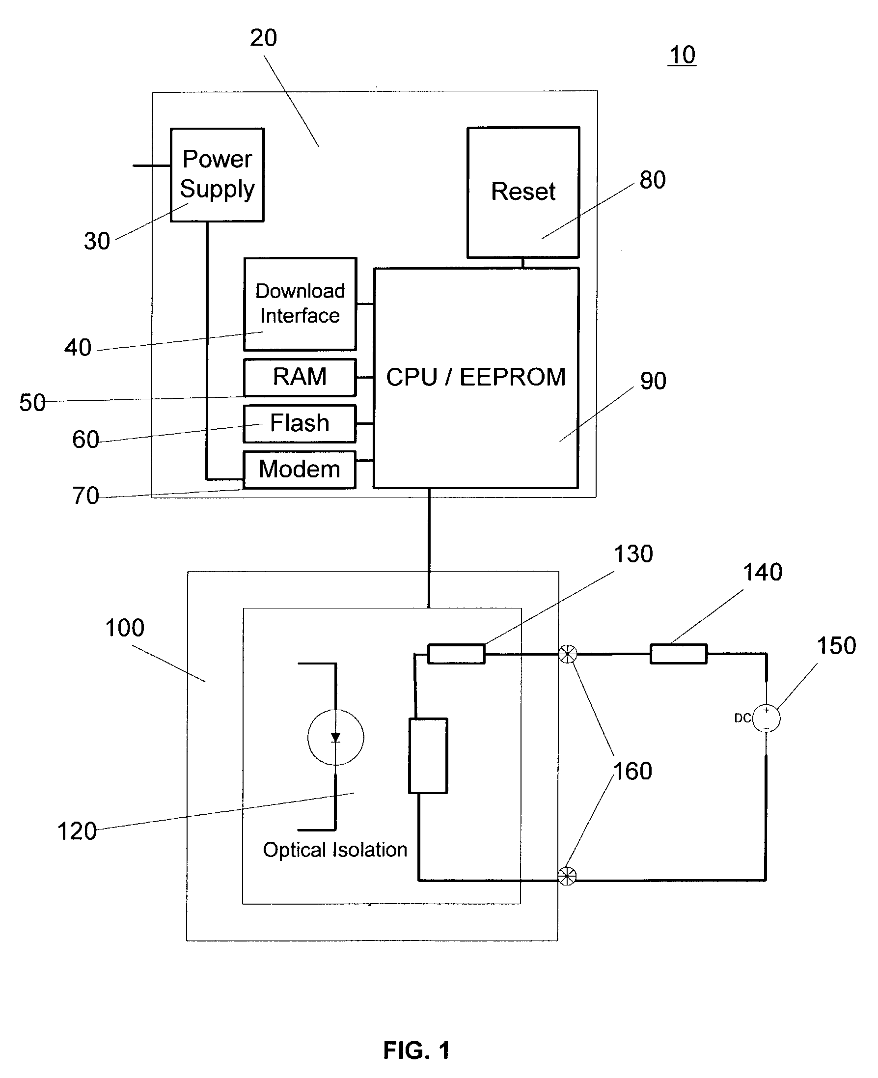
[0029]FIG. 1 shows a first exemplary embodiment of a fieldbus relay arrangement 10 according to the present invention. This exemplary fieldbus relay arrangement 10 includes a main circuit board 20 which has coupled thereto or contains therein certain components such as power supply and signal shaper 30, a firmware download interface 40, a flash memory 50, a random access memory (RAM) 60, a modem 70, a factory reset module 80, as well as a central processing unit (CPU) with electrically erasable programmable read-only memory (EEPROM) 90. In addition to the main circuit board 20, the relay arrangement 10 may include a relay apparatus 100 that has an optical isolation circuit 120 and a fuse 130. Output connectors 160 are provided for connecting a load 140 and a power supply 150 in parallel wi...


PUM


Abstract

An arrangement operable to communicate with a fieldbus network and operate an attached relay and a method for implementing such arrangement is provided. The arrangement and method provide conventional discrete outputs from a fieldbus device using standard fieldbus function blocks, such as those used for Foundation® and Profibus® fieldbus networks. The arrangement and method may facilitate the integration of traditional discrete relay functions into these more advanced digital fieldbus networks, and also utilize additional functions available to standard Foundation® fieldbus and Profibus® fieldbus network devices.

Description

FIELD OF THE INVENTION[0001]The present invention relates generally to a fieldbus relay arrangement. In particular, the invention is directed towards a fieldbus relay arrangement and method for implementing such arrangement which makes discrete outputs available using standard function blocks in Foundation® fieldbus and Profibus® fieldbus networks, and which can further utilize the additional functions available to standard Foundation® fieldbus and Profibus® fieldbus network devices.BACKGROUND OF THE INVENTIONThe Use of Fieldbus for Process Control Applications[0002]Process control systems and methods provide a way for ensuring efficiency, reliability, profitability, quality and safety in a process / product manufacturing environment. Such process control systems and methods can be used for automation, monitoring and control in a wide array of industrial applications for many industry segments, including textiles, glass, pulp and paper, mining, building, power, sugar, food and beverag...

Claims


Application Information

Patent Timeline
Patent Type & Authority Patents(United States)
IPC IPC(8): G05B15/00G05B19/042G06F17/00
CPCG05B19/0423H04L12/403G05B2219/25014G05B2219/25242G05B2219/25428H04L2012/4026H04L41/00H04L2012/40221H04L12/24
Inventor CASSIOLATO, CESARDE OLIVEIRA, EDSON EMBOABADE SOUZA, LIBANIO CARLOSDULTRA, MARCELO LUIS
Owner SMAR RES CORP
Why Eureka
Try Eureka