
Function control for a processor

a processor and function control technology, applied in specific access rights, hardware monitoring, television systems, etc., can solve the problem that the access to the control value may need to be limited, and achieve the effect of preventing access and simple and effective

Active Publication Date: 2007-06-12
ARM LTD
View PDF15 Cites 20 Cited by
  • Summary
  • Abstract
  • Description
  • Claims
  • Application Information

AI Technical Summary

Benefits of technology

[0004]The present invention recognises that the ability to be able to input control values to a processor via an input port is a strong and effective tool in the control of a processor, which may have disadvantages as it may allow radical changes to the control of the system that may not be desirable. The ability to be able to disable access to the control value therefore enables this strong and effective tool to be turned off under certain circumstances and provides an additional level of control to the system. Thus, a powerful and effective tool for control of the processor can be made available and unavailable according to circumstances. For example, access to the control value may need to be limited if access to certain data from certain activities is to be effectively inhibited. In the present invention the ability to input the control value via an input port, when an access control signal allows it, provides a simple and direct way of changing the control value and thus in some examples the access rights of some functions. The invention also however provides a way of preventing access to the control value via this input port should this be desirable. Thus, a particularly efficient and yet potentially secure way of allowing access to the control value is provided.
[0009]In order to be able to monitor processors to find any faults that may be present monitoring functions such as debug and trace applications have been developed. In order for these applications to be able to function properly, these applications have conventionally had access to the entire processor. This is generally needed as it allows the monitoring functions to locate a fault that may be anywhere on the processing system. With processors that operate in more than one domain, allowing a monitoring application access to the entire processor enables it to find a fault located anywhere on the system. However, such a comprehensive monitoring function may also allow data movement or leakage between the two domains. However, not allowing debug or trace to access certain parts of a system, makes it difficult, if not impossible, to locate certain faults that may occur in a non-accessible part of the system.
[0012]The present invention is particularly suitable for use in a processor having a secure and a non-secure domain. Monitoring functions that generally access the whole system can introduce weaknesses into the security of such a system. Providing control over the capture of diagnostic data can improve the security of such systems.
[0018]In some embodiments the input port comprises an input port on a JTAG controller. JTAG is a conventional way to remove and input debug data via a serial scan cell chain. At least one input port for providing debug instructions is provided on a JTAG. One of these input ports may be conveniently be used to provide access to a storage element containing a control value. Providing a means to control and at times prevent access to the control value provides a vital degree of security to the system.
[0020]A convenient and simple way of permanently preventing access via the input port to the control value stored in the storage element is to permanently tie the access control signal to the predetermined level. The use of a logic gate to prevent access to a control value via an input port when the access control value is set at a predetermined level is a simple and effective way of preventing access.

Problems solved by technology

For example, access to the control value may need to be limited if access to certain data from certain activities is to be effectively inhibited.

Method used


Image

  • Function control for a processor
  • Function control for a processor
  • Function control for a processor

Examples


Embodiment Construction

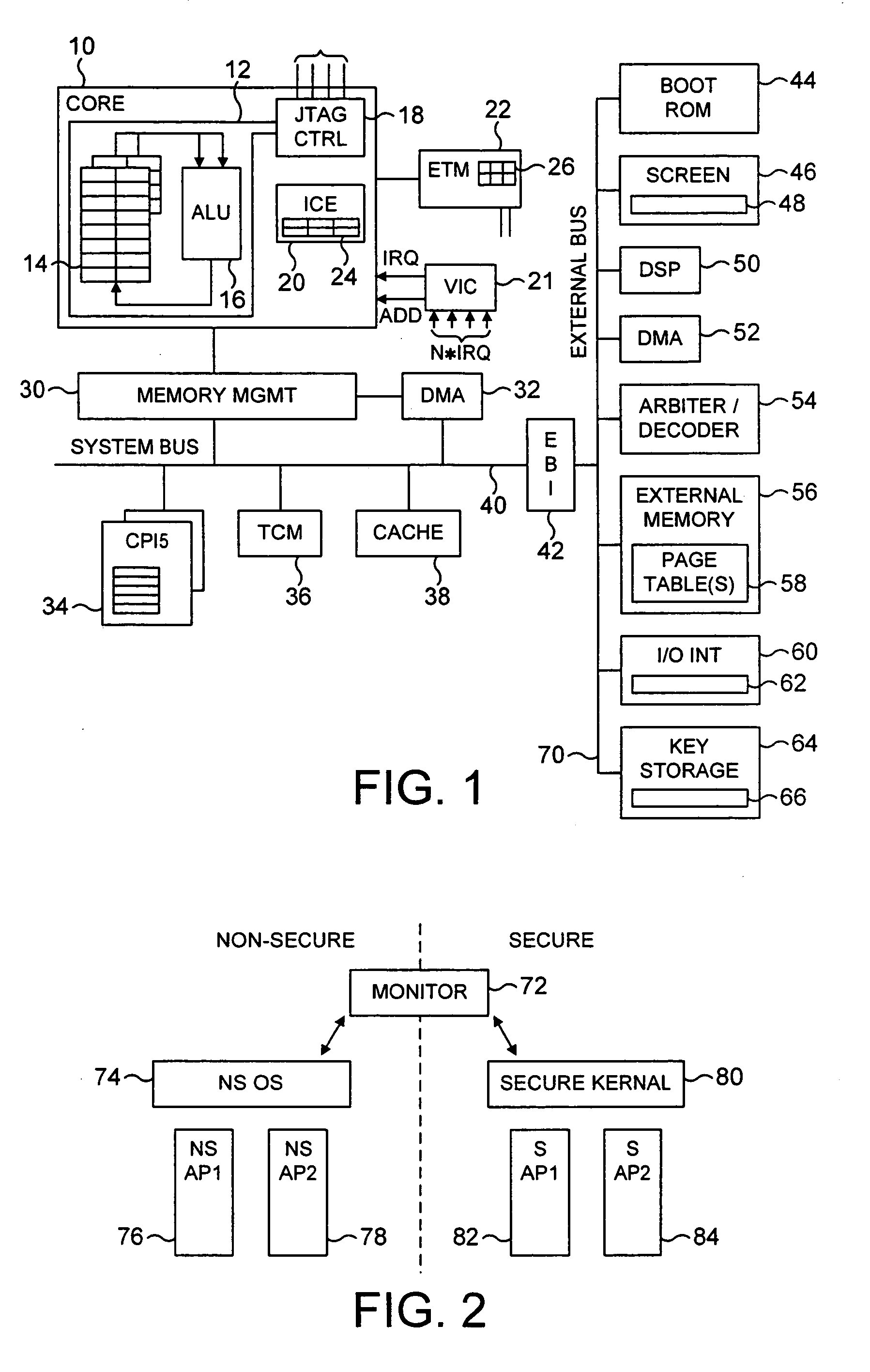
[0092]FIG. 1 is a block diagram illustrating a data processing apparatus in accordance with preferred embodiments of the present invention. The data processing apparatus incorporates a processor core 10 within which is provided an arithmetic logic unit (ALU) 16 arranged to execute sequences of instructions. Data required by the ALU 16 is stored within a register bank 14. The core 10 is provided with various monitoring functions to enable diagnostic data to be captured indicative of the activities of the processor core. As an example, an Embedded Trace Module (ETM) 22 is provided for producing a real time trace of certain activities of the processor core in dependence on the contents of certain control registers 26 within the ETM 22 defining which activities are to be traced. The trace signals are typically output to a trace buffer from where they can subsequently be analysed. A vectored interrupt controller 21 is provided for managing the servicing of a plurality of interrupts which...


PUM


Abstract

A processor operable to perform a plurality of functions, the processor comprising: an input port; a storage element operable to receive and to store an input signal input via the input port, the input signal comprising at least one control value; control logic operable to control at least one of the functions of the processor in dependence on the at least one control value; and access logic operable to receive an access control signal and to disable access via the input port to the at least one control value stored in the storage element in dependence upon the access control signal.

Description

FIELD OF THE INVENTION[0001]The present invention relates to the field of controlling a processor that performs a plurality of functions and in particular, in certain preferred embodiments, to the control of the debugging and tracing functions of such processors.DESCRIPTION OF THE PRIOR ART[0002]The control of a computer may be aided by the use of control values. These control values can be used to provide an indication as to whether particular functions of a computer are available or are to be performed in a particular way. Generally, these control values are input via software, although it may be possible in some processors to input the values via hardware input ports. The input of control values is a powerful tool and can provoke radical changes to the operation of the processor.SUMMARY OF THE INVENTION[0003]A first aspect of the present invention provides a processor operable to perform a plurality of functions, the processor comprising: an input port; a storage element operable...

Claims


Application Information

Patent Timeline
Patent Type & Authority Patents(United States)
IPC IPC(8): G06F11/30G06F9/46
CPCG06F9/468
Inventor WATT, SIMON CHARLESORION, LUCCHAUSSADE, NICOLAS
Owner ARM LTD
Learn More