
Method and apparatus for tuning a PID controller

a pid controller and controller technology, applied in the direction of electric controllers, controllers with particular characteristics, data processing applications, etc., can solve the problems of source of inaccuracy, signalization errors in the ultimate gain and ultimate frequency approximation, etc., and achieve the effect of eliminating the source of inaccuracy—on, simple analytical formulas

Inactive Publication Date: 2006-04-25
IMB CONTROLS
View PDF21 Cites 25 Cited by
  • Summary
  • Abstract
  • Description
  • Claims
  • Application Information

AI Technical Summary

Problems solved by technology

Despite the apparent success of autotune identification, it can lead to signification errors in the ultimate gain and ultimate frequency approximation (e.g., 5–20% error in R. C. Chiang, S. H. Shen, C. C. Yu, “Derivation of Transfer Function from Relay Feedback Systems”, Ind.
Several attempts were proposed to overcome this inaccuracy but didn't overcome the main source of inaccuracy—linear approximation of the relay element due to the use of describing function method model.

Method used


Image

  • Method and apparatus for tuning a PID controller
  • Method and apparatus for tuning a PID controller
  • Method and apparatus for tuning a PID controller

Examples


example

[0086]The following example illustrates an application of the method as well as is realized with the software, which actually implements the described algorithm and formulas.

[0087]Let the process be described by the following transfer function, which is considered unknown to the autotuner and is different from the process model used by the autotuner:

W(s)=0.5 exp(−0.6 s) / (0.8 s2+2.4 s+1)

[0088]The objective is to design a PI controller for this process with the use of first order plus dead time transfer function as an approximation of the process dynamics.

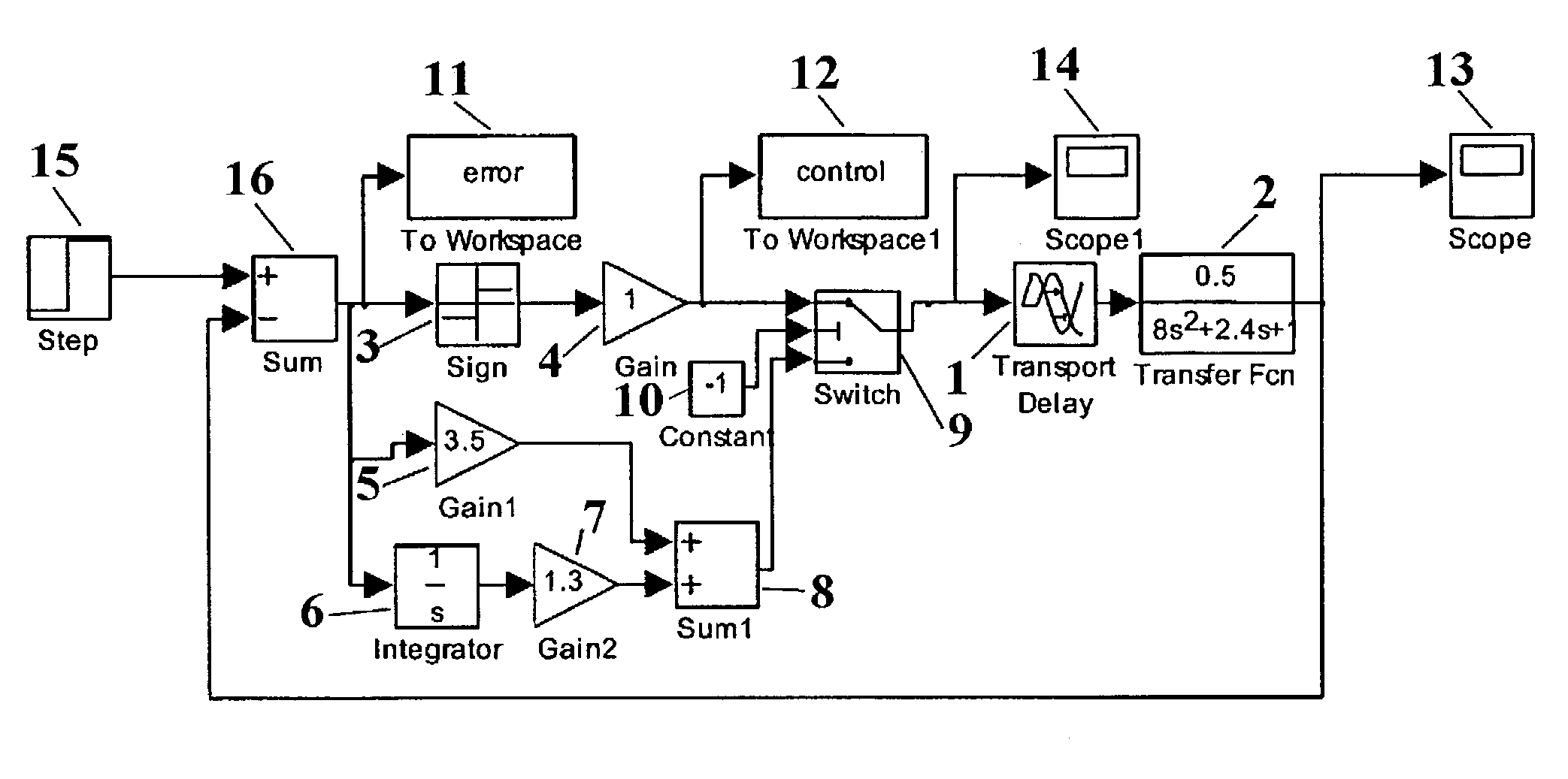
[0089]Simulations of the asymmetric relay feedback test and of the tuned system are done with the use of software SIMULINK® (of MathWorks). The block diagram is depicted in FIG. 6. Blocks Transport Delay 1 and Transfer Fcn 2 realize process model. The control is switched from the relay control (blocks Sign 3 and Gain 4) for the asymmetric relay feedback test to PI control (blocks Gain15, Integrator 6, Gain27, Sum18) by the Switch 9 d...


PUM


Abstract

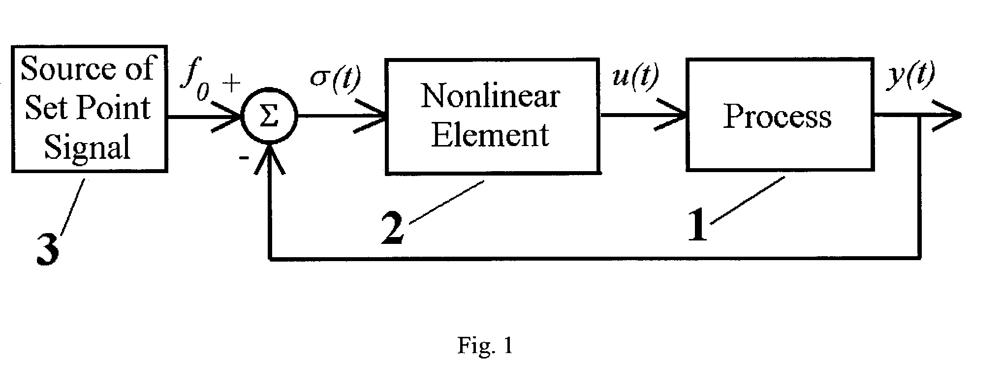
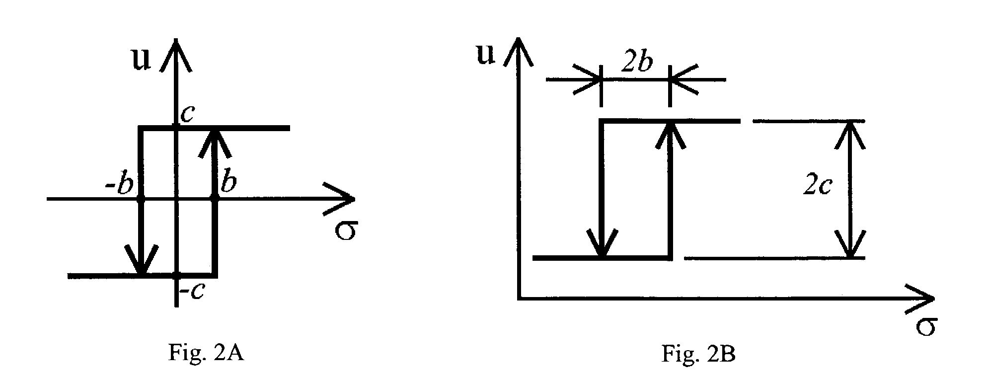
In tuning a controller for a process in a feedback control system, a method is provided for bringing the system into asymmetric self-excited oscillations for measuring the frequency of the oscillations, average over the period value of the process output signal and average over the period control signal and tuning the controller in dependence of the measurements obtained. An element having a non-linear characteristic is introduced into the system in series with the process and set point signal is applied to excite asymmetric self-excited oscillations in the system. An algorithm and formulas are given for identification of the process model having the form of first order plus dead time transfer function. PI controller settings are given as a function of the dead time / time constant ratio. An apparatus for performing the method is disclosed.

Description

[0001]CROSS-REFERENCE TO RELATED APPLICATIONSU.S. Patent Documents:4214300July 1980Barlow et al.364 / 105.4549123October 1985Hagglund et al.364 / 157.4602326July 1986Kraus364 / 158.4754391June 1988Suzuki364 / 157.4836319June 1989Haseda et al.180 / 142.Re33267July 1990Kraus364 / 158.5124626June 1992Thoen364 / 161.5222022June 1993Adams et al.364 / 431.5223778June 1993Svarovsky et al.364 / 157.5229699July 1993Chu et al.364 / 162.5283729February 1994Lloyd364 / 157.5311421May 1994Nomura et al.364 / 157.5325288June 1994Satou364 / 162.5396415March 1995Konar et al.364 / 162.5412557May 1995Lauw363 / 37.5453925September 1995Wojsznis et al.364 / 157.5535117July 1996Hiroi364 / 158.5568377October 1996Seem et al.364 / 157.5587899December 1996Ho et al.364 / 157.5587896December 1996Hansen et al.700 / 285742503April 1998Yu700 / 425649062July 1997Teng et al.706 / 23OTHER REFERENCES[0002]Cheng et al., 1999, Identification and Control of Nonlinear Systems Using Multiple Models: Relay Feedback Approach. Proc. American Control Conference 1999, 332...

Claims


Application Information

Patent Timeline
Patent Type & Authority Patents(United States)
IPC IPC(8): G05B13/02G05B11/42G05B13/04
CPCG05B11/42G05B13/042Y10S706/903Y10S706/906
Inventor BOIKO, IGOR
Owner IMB CONTROLS
Learn More