
Storage control system and method

a control system and storage technology, applied in the field of storage control system and method, can solve the problems of low reliability, low performance of disk devices, and inability to stop programs for a long time, so as to minimize the influence of storage devices and minimize the drop of processing speed

Active Publication Date: 2006-04-25
HITACHI LTD
View PDF5 Cites 22 Cited by
  • Summary
  • Abstract
  • Description
  • Claims
  • Application Information

AI Technical Summary

Benefits of technology

This approach minimizes the performance drop during data synchronization between high and low performance devices, maintaining system availability and efficiency by dynamically adjusting data allocation based on usage and performance thresholds, thus optimizing storage capacity utilization and reliability.

Problems solved by technology

In this case, consistency of data must be guaranteed during the copying operation, because if the copied data is updated during the copying operation, a mismatch of data occurs, and the backup becomes meaningless.
But in case of a system for which high availability is required, programs cannot be stopped for a long time.
Disk devices include high reliability high performance disk devices which are expensive but which have high reliability and performance, and low reliability low performance disk devices which are inexpensive but which have a lower reliability and performance than high reliability high performance disk devices.
Also the performance of the ATA disk device becomes a bottleneck when the volume copy is acquired or when mirror resynchronization is performed.
Such problems could occur when the attribute levels of the data write destination storage devices, such as performance or reliability, are apart.

Method used


Image

  • Storage control system and method
  • Storage control system and method
  • Storage control system and method

Examples


Embodiment Construction

[0053]An embodiment of the present invention will now be described with reference to the drawings.

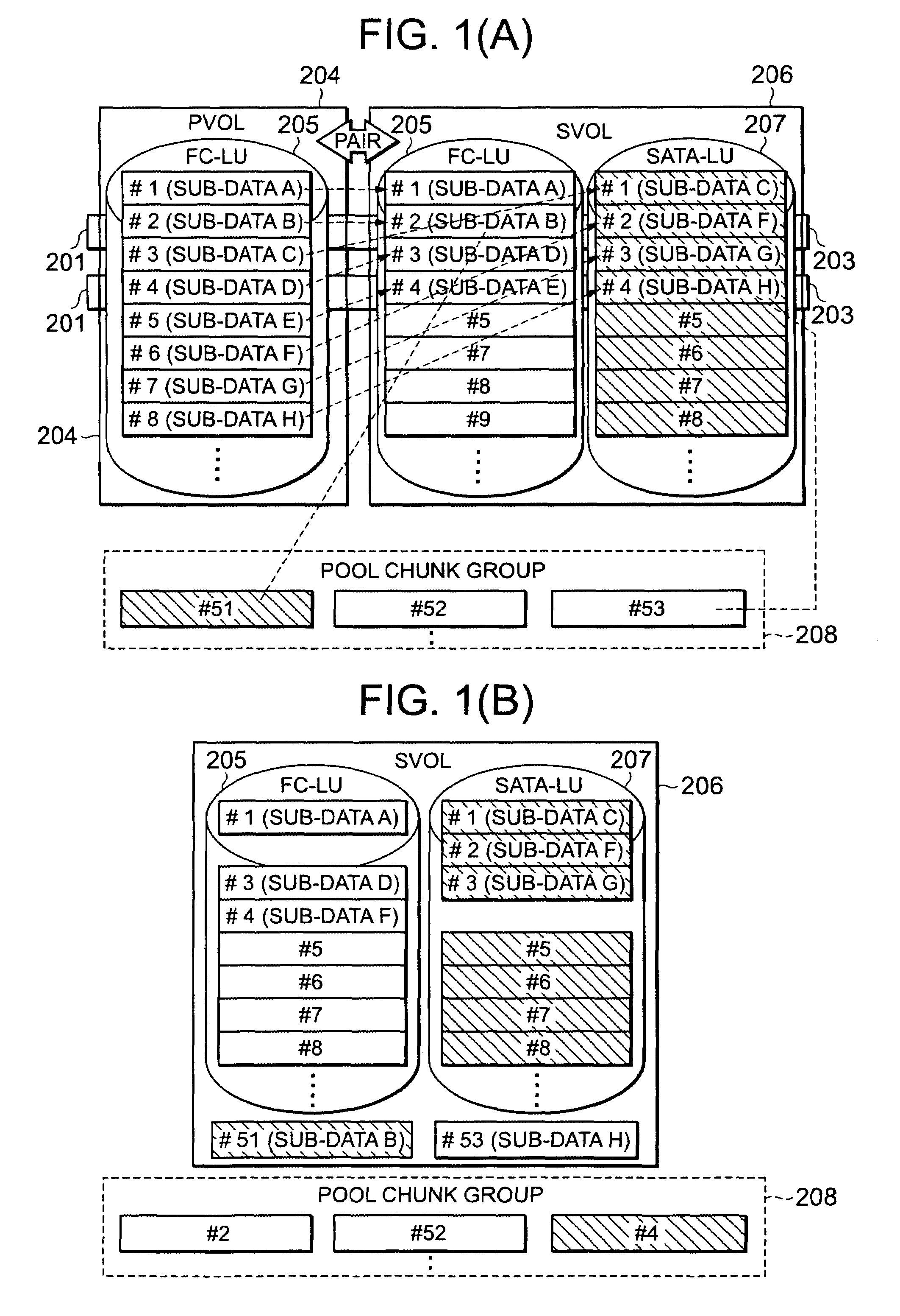
[0054]FIG. 1 is a diagram depicting the concept of the present embodiment. The concept of the present embodiment will be described first with reference to FIG. 1.

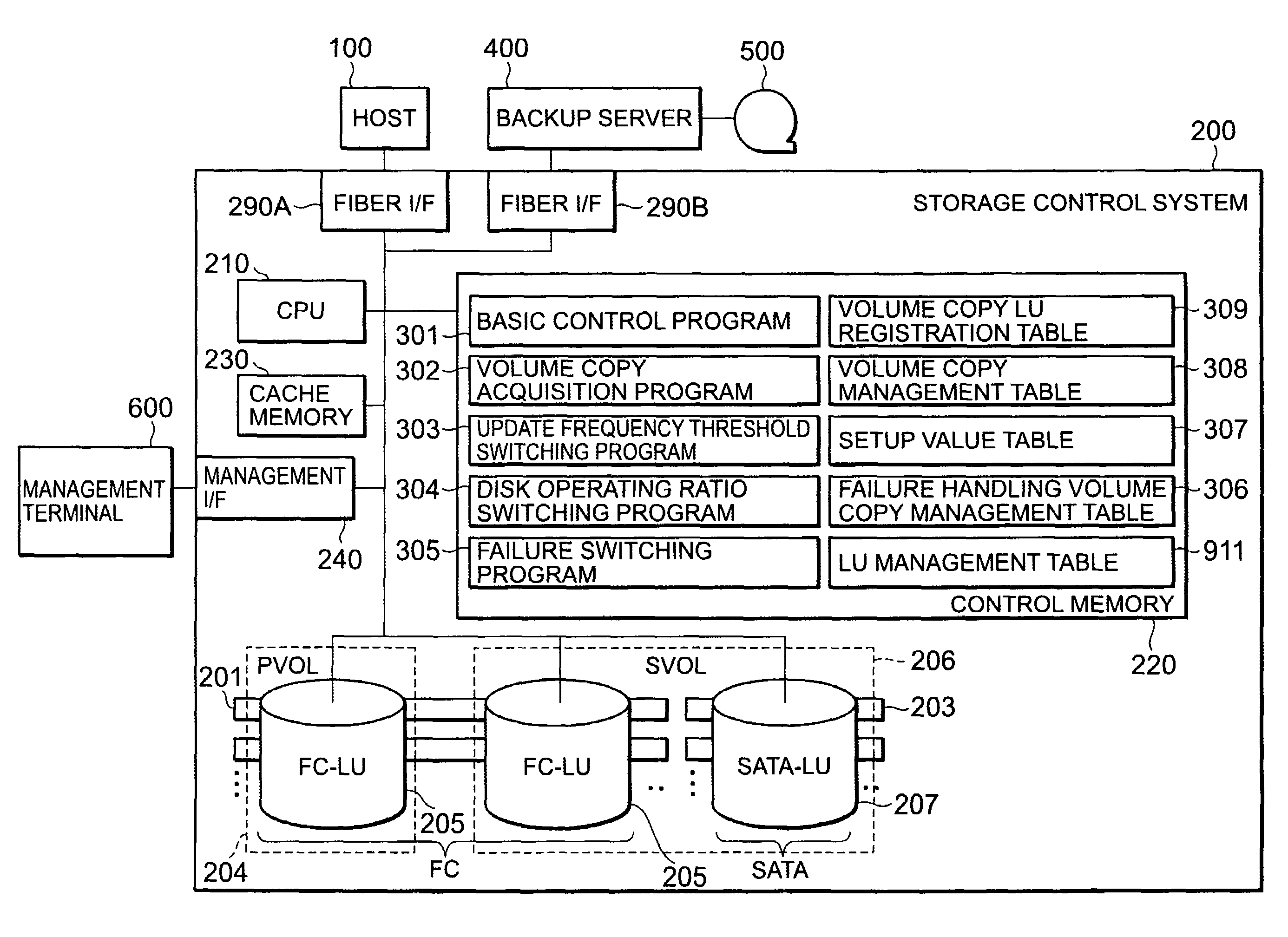
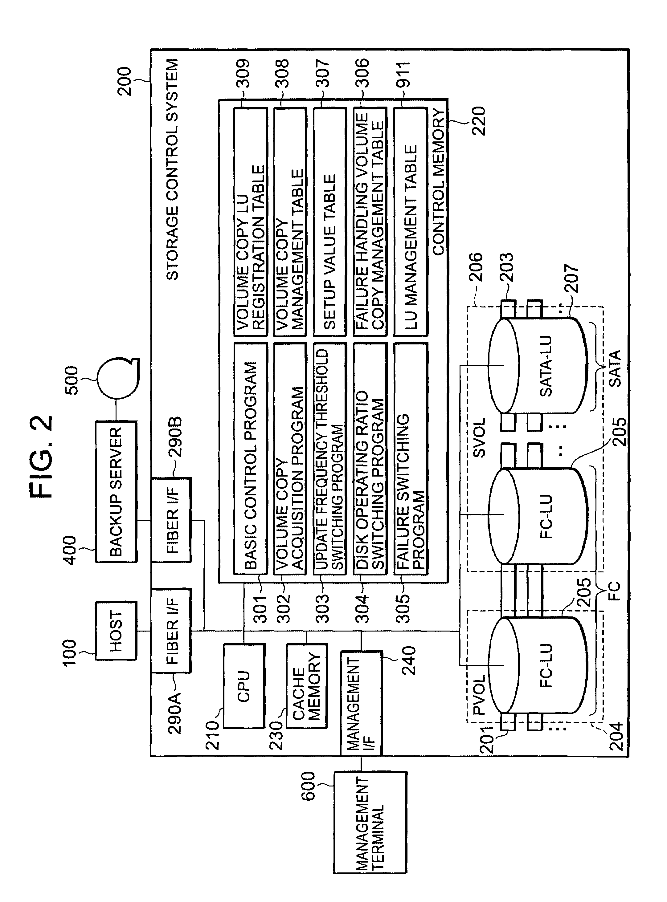
[0055]As FIG. 1(A) shows, in the present embodiment, a plurality of storage devices, where the attribute level of at least one of reliability and performance is different, coexist. In the plurality of storage devices, one or more fiber channel disk devices (hereafter “FC disk device”) 201, which are high reliability high performance disk devices, for example, are included as storage devices with a high attribute level. Also as a storage device with a low attribute level, one or more serial ATA disk devices (hereafter “SATA disk device”) 203, which have a low reliability low performance but which are less expensive than the FC disk device 201, are included. In the present embodiment, “reliability” refers to durability which can ...


PUM


Abstract

According to the present invention, each of a plurality of LUs existing on a storage control system 200 is divided into a plurality of chunks. A PVOL is comprised of only FC-chunks, but an SVOL is comprised of both FC-chunks and SATA-chunks. To each of the plurality of SVOL-chunks corresponding to the plurality of PVOL-chunks respectively, either an FC-chunk or SATA-chunk selected from a plurality of pool chunks is dynamically corresponded based on the update frequency of the sub-data of the corresponding PVOL chunk. Specifically, if an SVOL-SATA-chunk is corresponded to the PVOL-chunk of which the data update frequency is high, for example, the pool FC-chunk is corresponded as a sub-data swap destination in that SVOL-SATA-chunk.

Description

CROSS-REFERENCE TO PRIOR APPLICATION[0001]This application relates to and claims priority from Japanese Patent Application No. 2004-116069, filed on Apr. 9, 2004, the entire disclosure of which is incorporated herein by reference.BACKGROUND OF THE INVENTION[0002]1. Field of the Invention[0003]The present invention relates to a storage control system and method for controlling the storage of data to the storage device.[0004]2. Description of the Related Art[0005]In a system handling large amount of data, such as database system in a data center, data is managed using a storage control system that is built separately from the host computer. This storage control system is a disk array system, such as a RAID (Redundant Array of Independent / Inexpensive Disks), where many storage devices are enclosed in an array.[0006]In such a storage control system, backup for copying data recorded in the storage device to another storage device is performed so that the data can be recovered even if the...

Claims


Application Information

Patent Timeline
Patent Type & Authority Patents(United States)
IPC IPC(8): G06F17/30G06F3/06G06F12/00G06F17/00
CPCG06F3/0605G06F3/0644G06F3/067Y10S707/962Y10S707/99933Y10S707/99942Y10S707/99956Y10S707/99943
Inventor KEZUKA, TEIKOMUROTANI, AKIRAHIGAKI, SEIICHI
Owner HITACHI LTD
Learn More