Detailed placer for optimizing high density cell placement in a linear runtime

a linear runtime and cell placement technology, applied in the field of electronic design automation, can solve the problems of increasing the complexity of modem electronic circuits, the design is much too large for circuit designers or even designers to effectively manage manually, and the design is much too large for circuit designers or even designers to manage effectively. manual, and achieve the effect of optimizing cell placement, optimizing cell placement, and low density situations

Inactive Publication Date: 2006-04-25
SYNOPSYS INC
View PDF47 Cites 21 Cited by
  • Summary
  • Abstract
  • Description
  • Claims
  • Application Information

AI Technical Summary

Benefits of technology

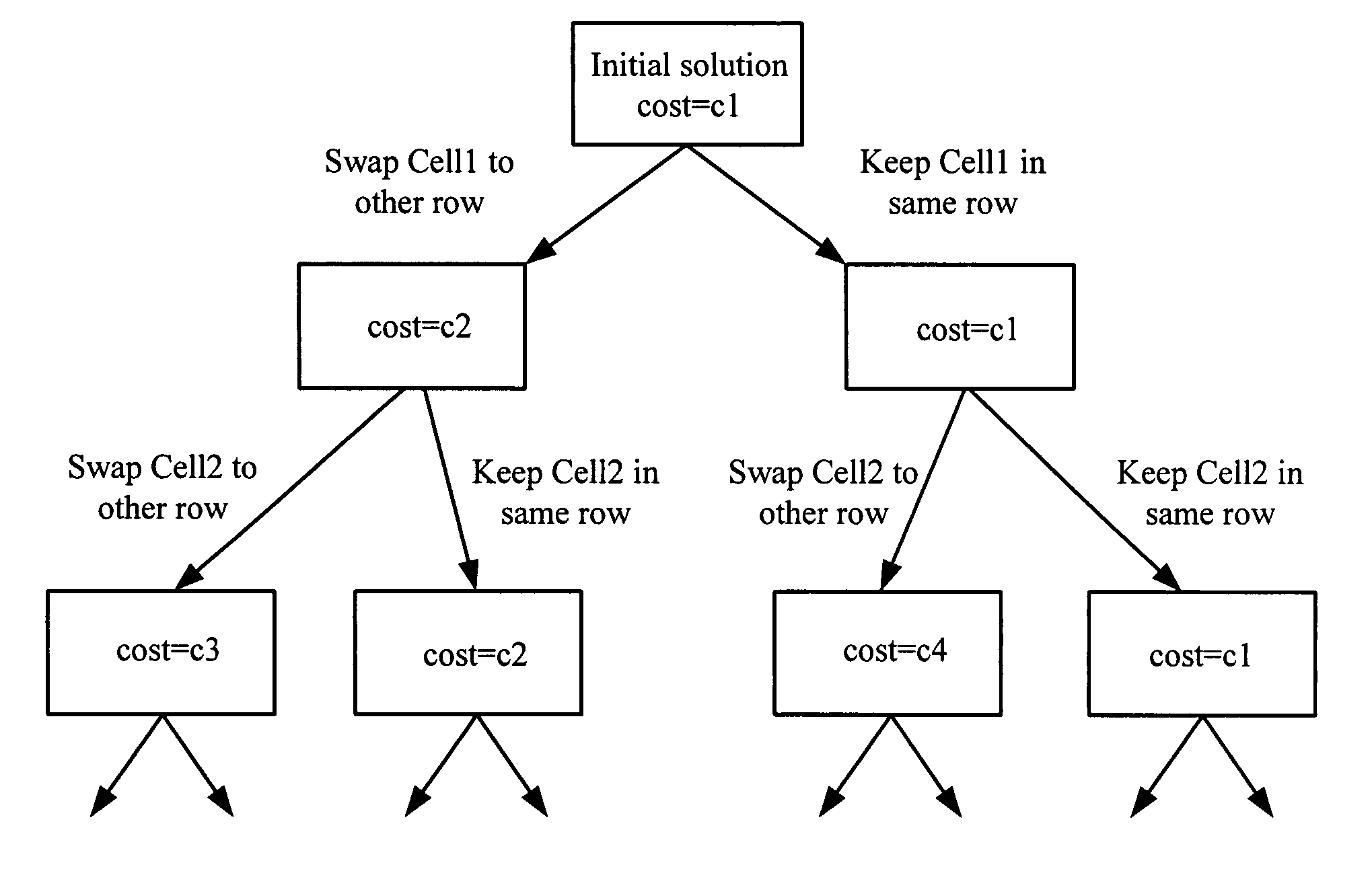
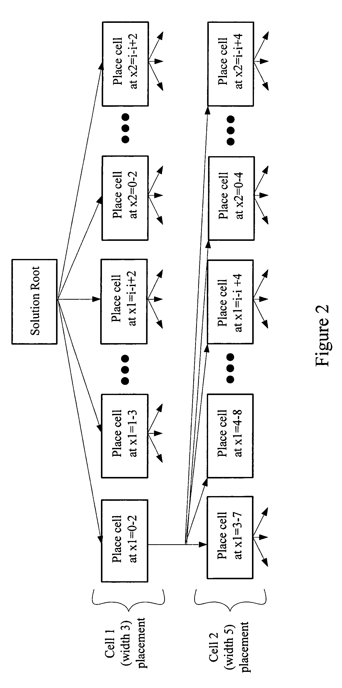
[0010]The present invention pertains to a detailed placement process which optimizes cell placement with up to one hundred percent densities in a linear run time. In one embodiment, the output from a conjugate-gradient coarse placement process is input to the detailed placement process. A dynamic programming technique is then used to optimize cell placement by swapping cells between two or more rows. The search space is pruned beforehand, and cells are snapped to one of the two rows. In another embodiment, a greedy cleanup phase using an incremental row placer is used. The incremental row placer judiciously places cells in a single row. The dynamic programming technique works well at optimizing cell placement when dealing with high density situations, and the greedy cleanup phase with the incremental row placer expeditiously optimizes the low density situations. Thereby, the detailed placer of the present invention handles congestion driven placements characterized by non-uniform densities very quickly and efficiently.

Problems solved by technology

The rapid growth in the complexity of modem electronic circuits has forced electronic circuit designers to rely upon computer programs to assist or automate most steps of the design process.
Such a design is much too large for a circuit designer or even an engineering team of designers to manage effectively manually.
One problem encountered with placement in general is that there are virtually countless different ways by which the cells of a given circuit can be arranged.
Another general problem is that course placement and detailed course placement processes have greater difficulty in placing cells at higher densities.
In other words, they cannot find solutions exceeding a certain density threshold.
This is disadvantageous as it delays time-to-market and also increases costs.

Method used


Image

  • Detailed placer for optimizing high density cell placement in a linear runtime
  • Detailed placer for optimizing high density cell placement in a linear runtime
  • Detailed placer for optimizing high density cell placement in a linear runtime

Examples


Embodiment Construction

[0040]An improved placement process is described. In the following description, for purposes of explanation, numerous specific details are set forth in order to provide a thorough understanding of the present invention. It will be obvious, however, to one skilled in the art that the present invention may be practiced without these specific details. In other instances, well-known structures and devices are shown in block diagram form in order to avoid obscuring the present invention.

[0041]When creating a layout for a given netlist, the present invention utilizes two phases: a first phase coarse placement process and a second phase detailed placement process. The first phase creates a placement using floating point numbers for the cell locations. This placement ignores may of the details, such as the exact site locations that the cells must map to, and generally creates a placement with a certain amount of overlapping cells. In the currently preferred embodiment of the present inventi...


PUM


Abstract

A detailed placement process which optimizes cell placement with up to one hundred percent densities in a linear run time. The output from a conjugate-gradient coarse placement process is input to the detailed placement process. A dynamic programming technique is used to optimize cell placement by swapping cells between two or more rows. The search space is pruned beforehand. A greedy cleanup phase using an incremental row placer is used. Thereby, the detailed placement process handles congestion driven placements characterized by non-uniform densities expeditiously and efficiently.

Description

[0001]This is a continuation of application Ser. No. 09 / 437,996 filed on Nov. 10, 1999 now abandoned, which is a Non-Provisional of patent application Ser. No. 60 / 159,687 filed Oct. 14, 1999, now U.S. Pat. No. 6,282,693.FIELD OF THE INVENTION[0002]The present invention relates to the field of electronic design automation (EDA). More specifically, the present invention relates to techniques for cell placement and other optimizations used in the design and fabrication of integrated circuit devices.BACKGROUND OF THE INVENTION[0003]The rapid growth in the complexity of modem electronic circuits has forced electronic circuit designers to rely upon computer programs to assist or automate most steps of the design process. Such a design is much too large for a circuit designer or even an engineering team of designers to manage effectively manually. Hence, circuits are almost always designed with the aid of an electronic design automation (EDA) system. Basically, and EDA system is a computer...

Claims


Application Information

Patent Timeline
Patent Type & Authority Patents(United States)
IPC IPC(8): G06F17/50
CPCG06F17/5072G06F30/392
Inventor MILLER, RONALDNAYLOR, WILLIAMWONG, YIU-CHUNG
Owner SYNOPSYS INC
Why Eureka
Try Eureka