

QCM sensor and QCM sensor device
a technology of qcm sensor and qcm, which is applied in the direction of vibration measurement in solids, generator/motor, instruments, etc., can solve the problems of long time required for one measurement point, and long time required for measuremen
- Summary
- Abstract
- Description
- Claims
- Application Information
AI Technical Summary
Benefits of technology
Problems solved by technology
Method used
Image

Examples
first embodiment
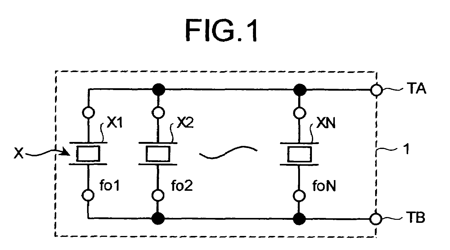
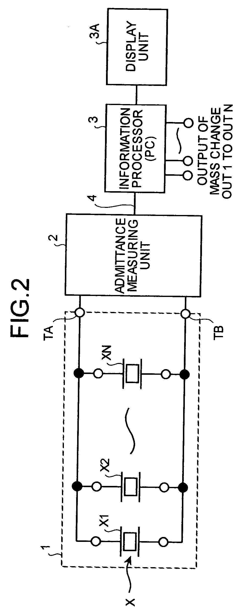
[0051]FIG. 1 is a diagram of a QCM sensor in a QCM sensor device according to the present invention. FIG. 2 is a diagram of structure of the QCM sensor device.
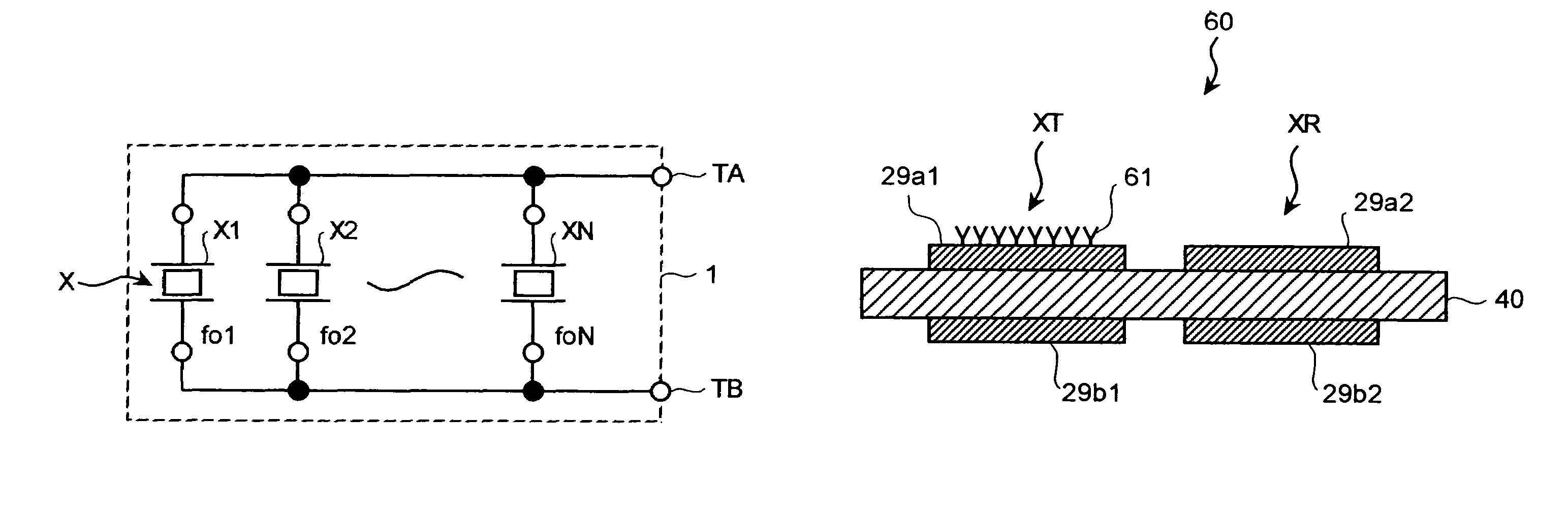
[0052]A QCM sensor 1 includes a plurality of AT-cut quartz crystal resonators X (X1, X2, . . . , XN) which are piezoelectric transducers. The quartz crystal resonators X1, X2, . . . , XN have resonance frequencies fo1, fo2, . . . , foN, respectively. The quartz crystal resonators are connected in parallel with each other and one electrode of each quartz crystal resonator is connected to a connecting terminal TA and other electrode of each quartz crystal resonator is connected to a connecting terminal TB.
[0053]The connecting terminals TA and TB are connected to two measuring terminals of an admittance measuring unit 2 (see FIG. 2). Because the quartz crystal resonators X1, X2, . . . , X3 are connected in parallel, the admittance measured in the admittance measuring unit 2 is a combined admittance of all the quartz crystal reson...
second embodiment
[0117]FIG. 21 is a time chart of a change in the resonance frequency when measured by using the quartz crystal resonators according to the Time is plotted on the horizontal axis and frequency is plotted on the vertical axis. When the resonance frequency fo of each of the quartz crystal resonators X1 to X4 is same, as the time elapses, the number of resonance points changes as shown in FIG. 21. A buffer solution is introduced at time T0 in four wells (sample holders 26a1 to 26a4) shown in FIGS. 15 and 16 and the resonance frequency of the four quartz crystal resonators X1 to X4 is allowed to be stabilized. In this case, a change in the resonance frequency is ΔfB. When the sample is charged upon stabilizing of the resonance frequency, there are two resonance points during a period of time from T1 to T2 and three resonance points during a period of time from T2 to T3. Therefore, a method has to be devised for the measurement of the resonance frequency.
[0118]Since the resonance frequen...
third embodiment
[0129]the present invention is described below. The third embodiment differs from the first and the second embodiments in the configuration of the QCM sensor 1. FIG. 23 is a top view of a QCM sensor according to the third embodiment. FIG. 24 is a side view of the QCM sensor shown in FIG. 23. According to the third embodiment, four oscillating domains 53a1 to 53a4 are provided on a quartz substrate 40. Electrodes to drive each of the oscillating domains 53a1 to 53a4 are provided on a front surface and a rear surface of resonators, thereby forming four quartz crystal resonators X1 to X4 on the substrate 40.
[0130]Front electrodes and rear electrodes of the quartz crystal resonators X1 to X4 are connected collectively (in parallel) by common lines 52a and 52b on the quartz substrate 40 and are led out to connecting terminals (connecting pads) PA and PB. The sample need not be necessarily held in the sample holders 26a1 to 26a4 shown in FIGS. 15 and 16. For example, samples 54a1 to 54a4 ...
PUM
| Property | Measurement | Unit |
|---|---|---|
| frequency | aaaaa | aaaaa |
| frequency | aaaaa | aaaaa |
| resonance frequency | aaaaa | aaaaa |
Abstract
Description
Claims
Application Information