Electronically controlled throttle apparatus

a technology of electric control and throttle device, which is applied in the direction of electric control, mechanical equipment, machines/engines, etc., can solve the problems of shortening the service life of mechanical parts, increasing the cost of buffer mechanism, and reducing the effect of deteriorating buffer mechanism, so as to reduce mechanical collision noise and impact energy, reduce the risk of damage to motor or mechanical parts, and increase reliability

Inactive Publication Date: 2006-05-02
HITACHI LTD
View PDF14 Cites 16 Cited by
  • Summary
  • Abstract
  • Description
  • Claims
  • Application Information

AI Technical Summary

Benefits of technology

[0013]An object of the present invention is to provide an electronically controlled throttle control apparatus increased in reliability, involving no risk of damaging the motor or mechanical parts, and permitting reductions in mechanical collision noise and impact energy.

Problems solved by technology

Then the full open stopper of the throttle valve and drive mechanism parts will violently clash with each other, inviting problems of collision noise and an effect of the impact load to shorten the service life of mechanical parts.
However, the formula described in the Japanese Patent Laid-Open No. 2002-256892 involves the problems of the additional cost of the buffer mechanism, the reduced effect of a deteriorated buffer mechanism, and a loss in reliability due to the increased number of components.
Therefore, it has the possibility that the motor may continue to drive even if the throttle valve returns to its full open position, and an excess current may damage the motor or a consequent overload may work on and damage mechanical parts.

Method used


Image

  • Electronically controlled throttle apparatus
  • Electronically controlled throttle apparatus
  • Electronically controlled throttle apparatus

Examples


first embodiment

[0065]The configuration of an electronically controlled throttle apparatus (an electronic throttle apparatus) for diesel engines in carrying out the present invention will be described below with reference to FIG. 1 through FIG. 15.

[0066]First, the system of the electronic throttle apparatus in the embodiment will be described with reference to FIG. 1.

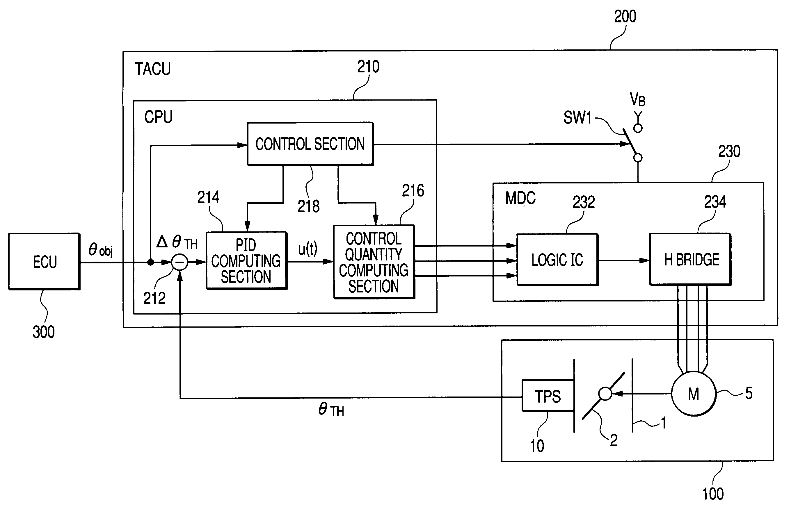
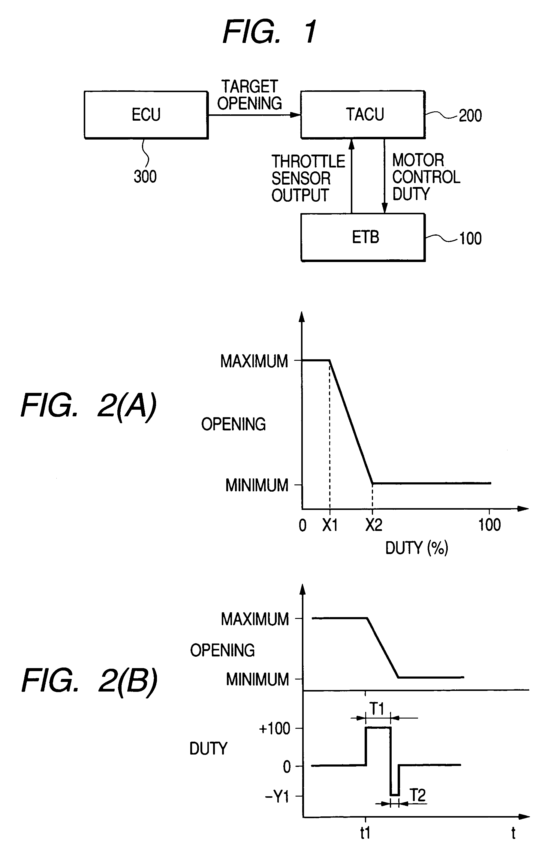
[0067]FIG. 1 shows the system of the electronic throttle apparatus in the first embodiment.

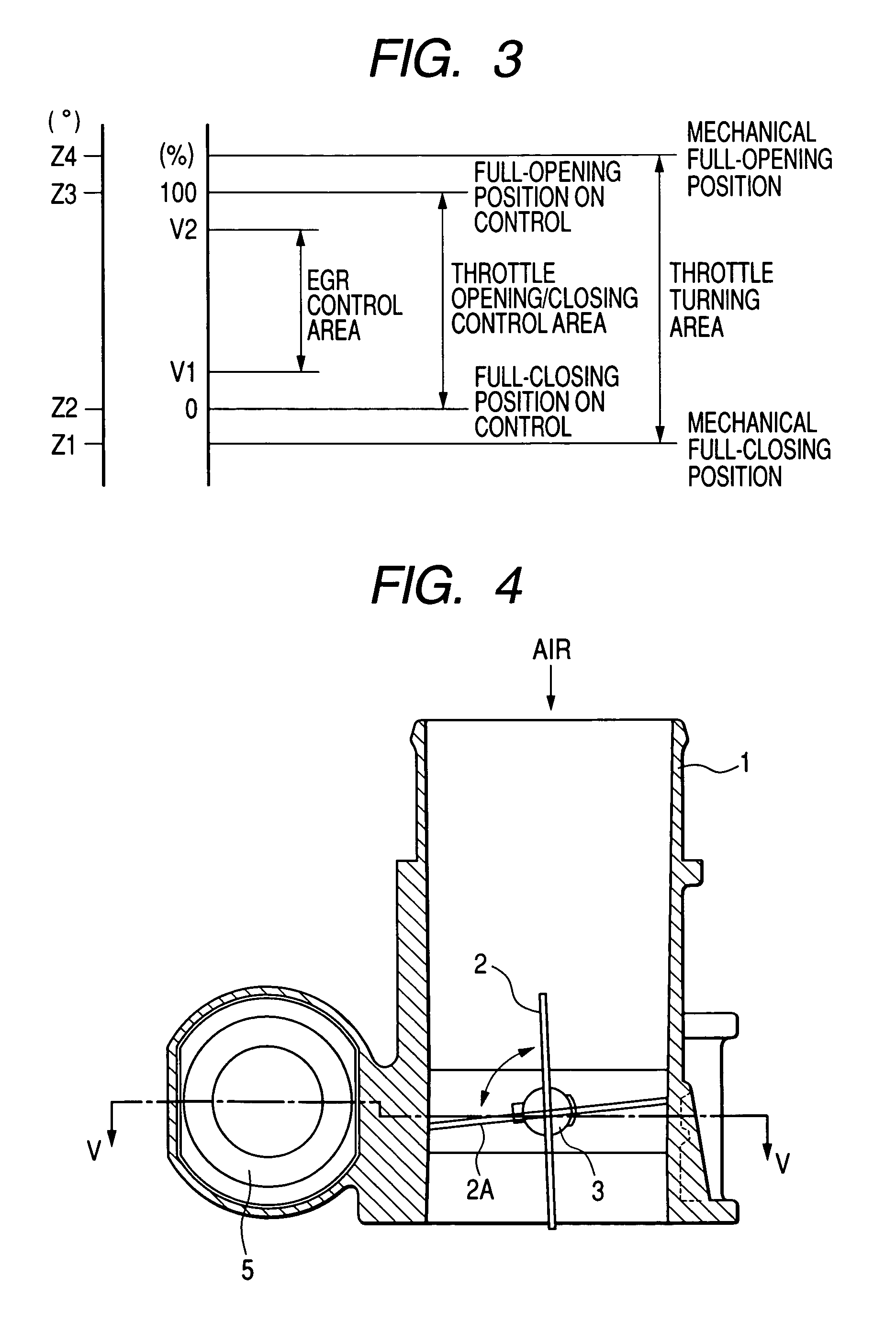
[0068]The electronic throttle apparatus is composed of an electronic throttle body (ETB) 100 and a throttle actuator control unit (TACU) 200. The electronic throttle body (ETB) 100 comprises a throttle valve rotatably held in a throttle body and an actuator, such as a motor, for driving this throttle valve. Its detailed configuration will be described afterwards with reference to FIG. 4 through FIG. 11.

[0069]The throttle actuator control unit (TACU) 200 controls the throttle valve of the electronic throttle body (ETB) 100 so that the opening ther...

second embodiment

[0123]Next, the control operation by the control section 218 of an electronic throttle apparatus in the invention will be described with reference to FIG. 16 and FIG. 17.

[0124]The system of the electronically controlled throttle apparatus (electronic throttle apparatus) in this embodiment is similar to what is shown in FIG. 1. Also, the configuration of the electronic throttle apparatus is similar to what is shown in FIG. 4 through FIG. 11. Further, the system of the throttle actuator control unit (TACU) 200 of the embodiment is similar to what is shown in FIG. 12. Also, the configuration of the H bridge circuit 234 for use in the electronic throttle apparatus is similar to what is shown in FIG. 13.

[0125]FIG. 16 is a flow chart showing the contents of controls by the control section of the electronic throttle apparatus in the second embodiment. FIG. 17 illustrates the time chart of controls by the control section. The same step numbers as in FIG. 14 denote respectively the same cont...

third embodiment

[0136]Next, the control operation by the control section 218 of an electronic throttle apparatus in the invention will be described with reference to FIG. 18.

[0137]The system of the electronic throttle apparatus in this embodiment is similar to what is shown in FIG. 1. Also, the configuration of the electronic throttle apparatus is similar to what is shown in FIG. 4 through FIG. 11. Further, the system of the throttle actuator control unit (TACU) 200 is similar to what is shown in FIG. 12. Also, the configuration of the H bridge circuit 234 for use in the electronic throttle apparatus is similar to what is shown in FIG. 13.

[0138]FIG. 18 is a flow chart showing the contents of controls by the control section of the electronic throttle apparatus. The same step numbers as in FIG. 14 and FIG. 16 denote respectively the same control contents.

[0139]In this embodiment, the processing at step s310 and step s320 is added to the controls charted in FIG. 16.

[0140]If it is determined at step s1...


PUM


Abstract

That is an electronically controlled throttle device comprising a throttle valve held rotatably in a throttle body; an actuator for driving the throttle valve; a return spring which gives a force to return the throttle valve in the full open direction; a throttle position sensor for detecting the opening of the throttle valve; and a throttle actuator control unit for driving the actuator based on the opening of the throttle valve detected by the throttle position sensor and a target opening. Wherein the throttle actuator control unit is provided with a control means which controls the actuator, when EGR control or DPF control has ended, so that the throttle valve turns toward the full open position in a longer period of time than the length of time in which the throttle valve is turned toward the full open position by the return spring only.

Description

CLAIM OF PRIORITY[0001]The present application claims priority from Japanese application serial no. 2003-370002 filed on Oct. 30, 2003, the contents of which are hereby incorporated by reference into this application.BACKGROUND OF THE INVENTION[0002]The present invention relates to an electronically controlled throttle device for electrically controlling the quantity of air intake to a vehicle-mounted engine, and more particularly to an electronically controlled throttle device suitable for a diesel engine.[0003]An electronically controlled throttle apparatus (electronic throttle apparatus) which controls the quantity of air intake into a gasoline engine by optimally driving an actuator (e.g. a DC motor, torque motor, or stepping motor) are already in use. Such an throttle apparatus controls the position of the throttle valve with an actuator so as to make it identical with a target opening computed according to the treading depth of the accelerator pedal or the operating state of t...

Claims


Application Information

Patent Timeline
Patent Type & Authority Patents(United States)
IPC IPC(8): F02D11/10F16K1/22F02M25/07F02B3/06F02D9/02F02D9/10F02D21/08F02D41/04F02D41/22F02D45/00
CPCF02D9/105F02D9/1065F02D11/107F02D11/10F02B3/06F02D2041/2037F02D41/0065F02D2009/024
Inventor KAMIMURA, YASUHIROUCHIYAMA, YASUHISANAKANO, SYUUICHI
Owner HITACHI LTD
Why Eureka
Try Eureka