Heat exchanger module

a technology of heat exchanger and cooling module, which is applied in the direction of indirect heat exchanger, air heater, light and heating apparatus, etc., can solve the problems of difficult to apply the prior art to the cooling module in which both are used, and achieve the effect of easy absorbing and easy mounting

Inactive Publication Date: 2006-05-02
DENSO CORP
View PDF20 Cites 23 Cited by
  • Summary
  • Abstract
  • Description
  • Claims
  • Application Information

AI Technical Summary

Benefits of technology

[0016]Due to this arrangement, if a hole in which the securing means 4 is inserted is larger than the diameter of the securing means 4 or is an elongated hol...

Problems solved by technology

Thus, it is difficult to apply the prior art to the cooling module in which both of the heat exchangers...

Method used


Image

  • Heat exchanger module
  • Heat exchanger module
  • Heat exchanger module

Examples


embodiment 1

[0032](Embodiment 1)

[0033]According to the present embodiment, a heat exchanger module of the present invention is applied to a cooling module in which a radiator for a vehicle, and an external heat exchanger of an air conditioner for a vehicle, are integrated.

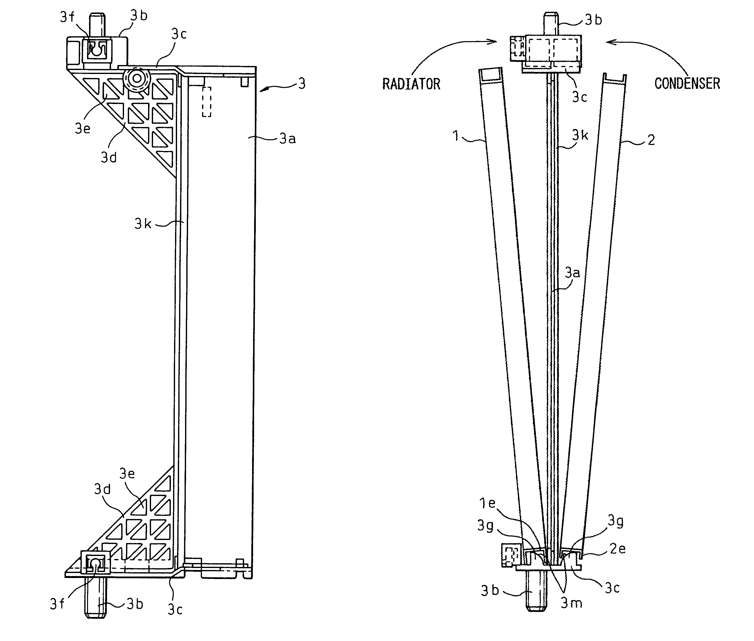
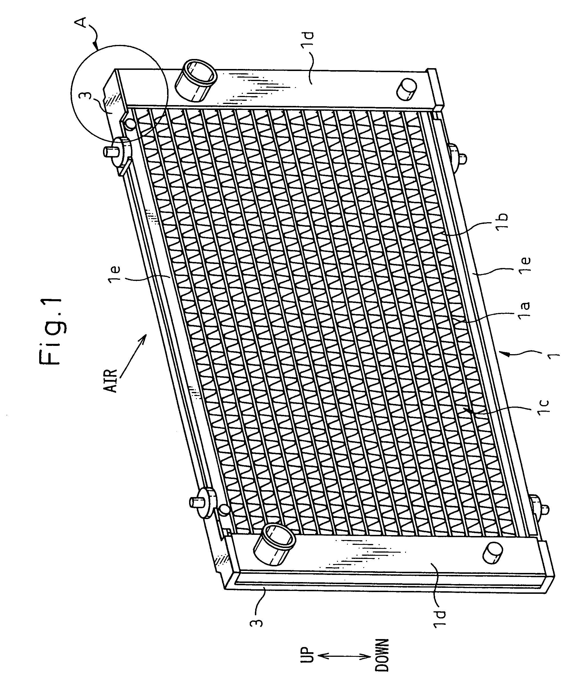
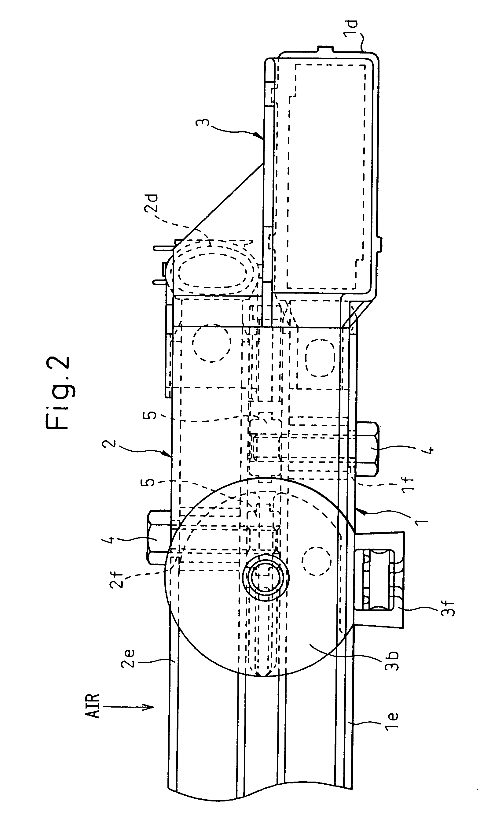
[0034]FIG. 1 is a perspective view of a cooling module of Embodiment 1 viewed from a downstream side of an air flow. FIG. 2 is a top view of A-part in FIG. 1. FIG. 3 is a front view of A-part in FIG. 1. FIG. 4 is a front view of a bracket 3.

[0035]A radiator 1 cools cooling water due to a heat-exchange between the cooling water circulating in an engine and the air. A condenser 2 (see FIG. 2) cools and condenses high-pressure refrigerant discharged from a compressor.

[0036]The radiator 1 and the condenser 2 are substantially identical in structure. In particular, as shown in FIG. 1, the radiator 1 and the condenser 2 are each comprised of a core 1c having a plurality of tubes 1a through which fluid, i.e., cooling water in the rad...

embodiment 2

[0063](Embodiment 2)

[0064]Though the radiator 1 and the condenser 2 are secured to the brackets 3 through the bolts 4 extending in a direction orthogonal to the core surfaces in Embodiment 1, according to the present embodiment, as shown in FIGS. 7A–7C, the condenser 2 is secured to the brackets 3 through the bolts 4′ extending parallel to the core surfaces.

[0065]The bracket bodies 3a are provided with stays 3j for fastening the condenser 2.

embodiment 3

[0066](Embodiment 3)

[0067]According to the present embodiment, as shown in FIGS. 8A–8C, the mounting stays if provided on the radiator 1 are united to the stays 3j, and both the radiator 1 and the condenser 2 are secured by fastening the bolts 4′.


PUM

PropertyMeasurementUnit
Efficiencyaaaaaaaaaa

Abstract

Brackets 3 made of resin are provided between the radiator 1 and the condenser 2, and the heat exchangers 1 and 2 are secured to the brackets 3, so that heat transfer from the radiator 1 to the condenser 2 can be restricted and reduction of the cooling efficiency of the condenser 2 can be prevented. The radiator 1 and the condenser 2 are assembled with and secured to the brackets 3 so that the position of the condenser 2 with respect to the radiator 1 can be easily determined. Therefore, the assembling of the cooling module can be facilitated and no heat exchange between the radiator 1 and the condenser 2 can be restricted due to a predetermined space provided between the core 1c of the radiator 1 and the core 2c of the condenser 2.

Description

BACKGROUND OF THE INVENTION[0001]1. Field of the Invention[0002]The present invention relates to a heat exchanger module, in which at least a first heat exchanger and a second heat exchanger are integrated with each other through brackets, and can be effectively applied to a cooling module in which a radiator for a vehicle and an external heat exchanger of an air conditioner for a vehicle are integrated.[0003]2. Description of the Related Art[0004]Conventionally, a radiator and a condenser are integrated by inserts (side plates) or fins, etc., and mounting brackets for mounting the same to a vehicle are secured to header tank portions (see Japanese Unexamined Patent Publication No. 11-142084, for example).[0005]Before making the radiator and the condenser integral with each other, the radiator and the condenser must be manufactured separately, because the specifications thereof are quite different.[0006]In this regard, according to a prior art disclosed in Japanese Unexamined Patent...

Claims


Application Information

Patent Timeline
IPC IPC(8): F28F9/02B60K11/04F28D1/04F28D1/053F28F9/00F28F21/06
CPCF28D1/0435F28F21/067F28F9/002
Inventor YAGI, YOSHINORIOZAKI, TATSUO
Owner DENSO CORP
Why Eureka
Try Eureka