Forced air bed warmer/cooler

a bed and cooler technology, applied in the field of bed warmers and bed coolers, can solve the problems of inconvenient use, shock or even electrocution, cumbersome and time-consuming device setting up, etc., and achieve the effect of enhanced and highly efficient warming and/or cooling of the bed environment, easy movement, and easy creation of pre-heating

Inactive Publication Date: 2006-05-02
RODNEY JAMES W
View PDF28 Cites 44 Cited by
  • Summary
  • Abstract
  • Description
  • Claims
  • Application Information

AI Technical Summary

Benefits of technology

[0029]The present invention recognizes and addresses particular disadvantages of prior art principles and constructions. Accordingly, it is an object of the present invention to provide enhanced and highly efficient warming and/or cooling of a bed environment. It is an object of this invention to provide a simple way to obviate the need for cumbersome warming/cooling envelopes, hoses, tubes, blankets or dangerous electrical wires in or over the bed, by operating as a single easily movable unit without additional separate external attachments. It is a further object of this invention to allow the user to maintain the comfortable, familiar bed coverings to which they are accustomed. By modifying the temperature of those coverings themselves as well as the air envelope created inside them, the total bed environment is made immediately comfortable to the user. It is a further object of this invention to easily create pre-heated or pre-cooled microenvironments within multiple undisturbed beds, without removal or disturbance of bed linens or coverings. It is also an object of this invention to introduce temperature-conditioned air into the bed by simply forcing the air into the space between the bed linens (e.g., between the bottom sheet and the bed covers). When activated, the pressure of the entering air causes the bed covers themselves to inflate slightly, thereby automatically distributing the warmed or cooled air to all parts of the bed. Another object of preferred embodiment of this invention is to complete an operational cycle and bring the bed interior to a comfortable temperature, before the occupant

Problems solved by technology

Moreover, the configuration of the unit is not such that the unit can be placed between the bottom sheet and bed cover with its handle overlapping the bed cover.
Moreover, the configuration of the unit is not such that the unit can be placed between the bottom sheet and bed cover with its handle o

Method used


Image

  • Forced air bed warmer/cooler
  • Forced air bed warmer/cooler
  • Forced air bed warmer/cooler

Examples


Embodiment Construction

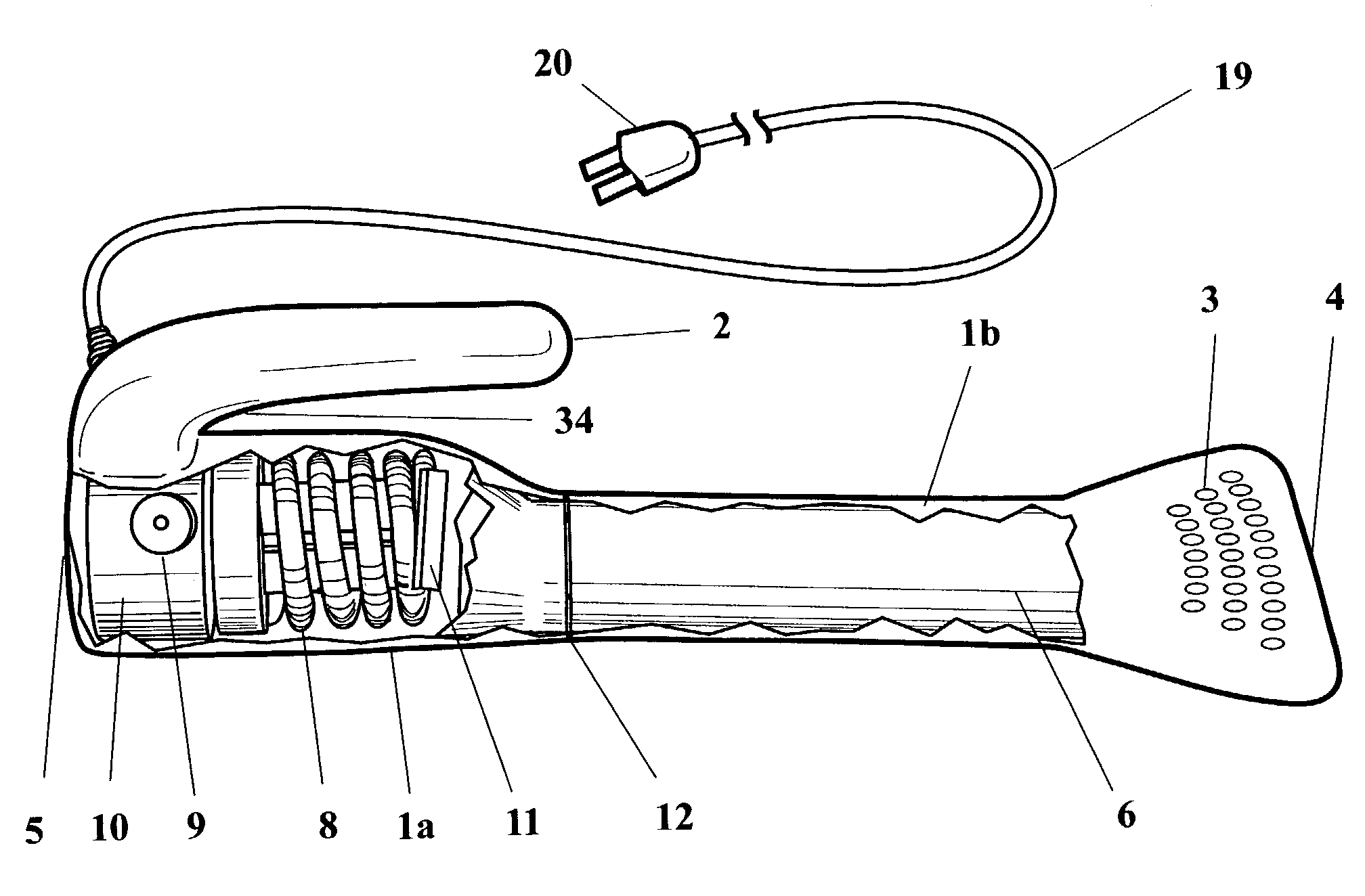
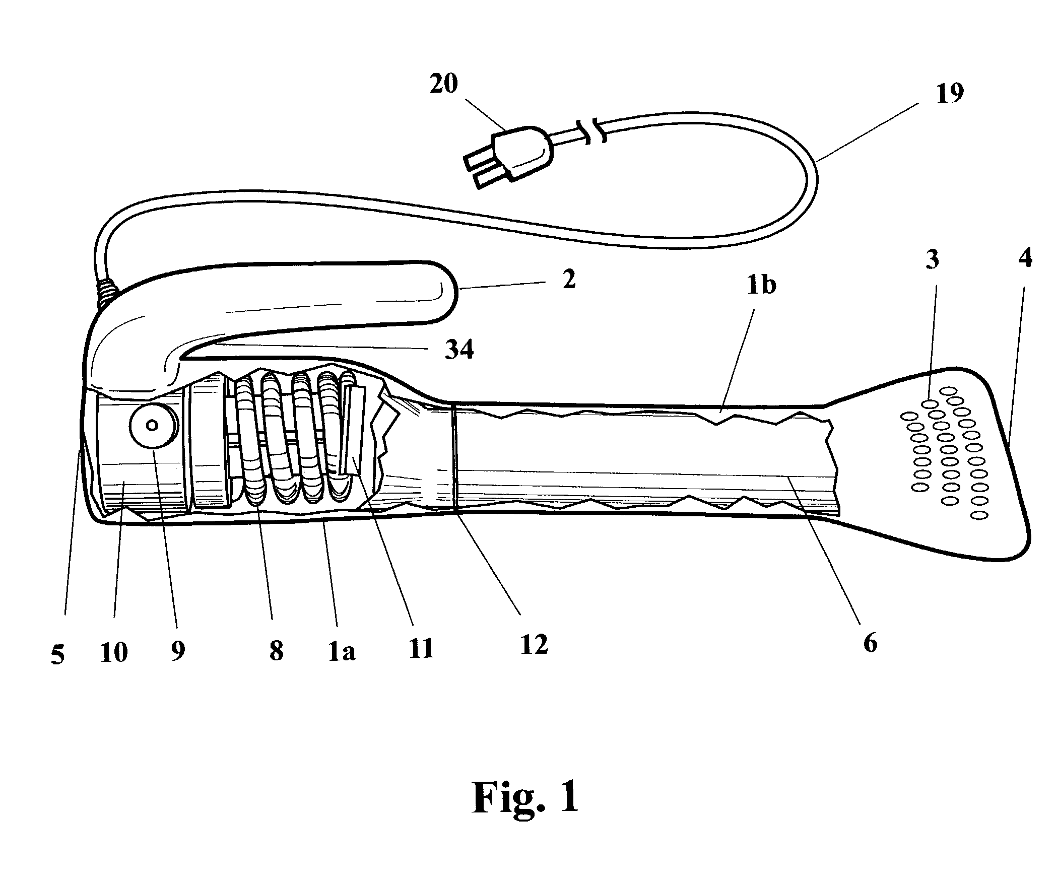
[0085]Referring to FIG. 1, a preferred embodiment of the invention is presented. This embodiment is designed to produce heating only and preferably comprises two main sections: heating element section 1a and air delivery section 1b which lock together via bayonet type joint 12. Heating element section 1a is generally cylindrical, with air intake 5 on one (rear) end and forward-projecting handle 2 attached at the top rear. The front of elongated air delivery section 1b is flattened into a flare that terminates in primary air exit 4. Patterns of holes on the top and bottom of the front flare serve as secondary air exits 3, providing auxiliary air exits for the device or alternative exits in the event that primary exit 4 becomes obstructed. Both heating element section 1a and air delivery section 1b are preferably constructed of a plastic, more preferably an injection-molded thermoplastic.

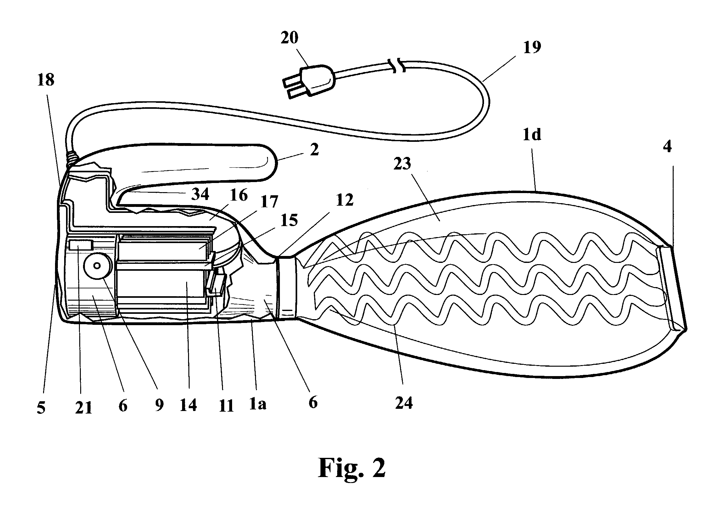
[0086]Mounted inside heating element section 1a are the following: high efficiency fan or other de...


PUM


Abstract

An apparatus and method for modifying the temperature of a bed environment. In preferred embodiments, the invention is a self-contained, forced air bed warmer which pre-heats the interior sheets and covers of a bed to provide a controlled micro-environment that facilitates relaxation into restful sleep on cold nights. Preferred embodiments include an air conditioning section comprising a body portion and a handle portion, said air conditioning section having an exterior surface that is adapted to receive an edge of a bed cover between said body portion and said handle portion; a fan; a heat transfer element; a temperature sensor; a control circuit connected to said temperature sensor; a timer mounted within said air conditioning section; and an elongated air delivery section having two ends with an air entrance at one end and a primary air exit at the other end.

Description

CROSS-REFERENCE TO RELATED APPLICATIONS[0001]This application claims the benefit of U.S. Provisional Application No. 60 / 365,438, filed Mar. 19, 2002; the disclosure of which application is incorporated by reference as if fully set forth herein.STATEMENT REGARDING FEDERALLY SPONSORED RESEARCH OR DEVELOPMENT[0002]Not applicableBACKGROUND OF THE INVENTION[0003]This invention relates to bed warmers and bed coolers. In particular, the invention relates to bed warmers and bed coolers that heat or cool the interior of a bed via the use of a directed flow of warm air or cool air.[0004]Bed warmers of various designs have been used for centuries to alleviate the discomfort of getting into a cold bed. More recently, devices have been created that both warm and cool the interior of a bed in an attempt to provide totally controlled temperature conditions within the bed.[0005]The background art is characterized U.S. Pat. Nos. 2,259,712; 2,560,349; 2,695,413; 3,230,556; 3,444,922; 3,713,182; 4,151...

Claims


Application Information

Patent Timeline
IPC IPC(8): F25B29/00A47C27/00
CPCA47C21/048
Inventor RODNEY, JAMES W.STRAUSS, TED N.
Owner RODNEY JAMES W
Why Eureka
Try Eureka