Method for attaching undercover onto underside of car floor panel

a technology for floor panels and undercovers, applied in the direction of threaded fasteners, roofs, transportation and packaging, etc., can solve the problems of troublesome operation and time-consuming, subject to distortion, and no assurance of avoiding thermally-induced distortions, so as to facilitate the attachment of an undercover and avoid thermally-induced distortions

Inactive Publication Date: 2006-05-02
NEWFREY
View PDF32 Cites 13 Cited by
  • Summary
  • Abstract
  • Description
  • Claims
  • Application Information

AI Technical Summary

Benefits of technology

[0008]It is therefore an object of the present invention to provide an undercover attaching apparatus and method that facilitate attaching an undercover and that allow the attached undercover to be desirably displaced along the underside of a floor panel due to thermal expansion and contraction, thereby avoiding thermally-induced distortion.
[0010]In one non-limiting embodiment of the invention, the fastener comprises a first clip including an outer tubular portion adapted to be inserted into the mounting hole of the undercover; and a second clip including an inner tubular portion adapted to be inserted into the outer tubular portion of the first clip, and an engagement member such as a pawl or pawls adapted to be engaged with the stud. The first clip is formed with a first flange adapted to be brought into contact with one side of the undercover when the outer tubular portion is inserted into the mounting hole; the second clip is formed with a second flange adapted to be brought into contact with the other surface of the undercover when the inner tubular portion is inserted into the outer tubular portion; and the outer and inner tubular portions are formed with first and second coupling portions for coupling the outer and inner tubular portions to one another, whereby when the outer tubular portion is inserted into the mounting hole of the undercover and then the inner tubular portion is inserted into the outer tubular portion to couple the first and second clips together by the coupling portions, the first and second flanges are brought into contact with respective sides of the undercover around the periphery of the mounting hole to clamp the undercover therebetween. The mounting hole of the undercover has a diameter substantially larger than the outer diameter of the outer tubular portion, providing diametral clearance that allows the undercover to be displaced along the underside of the floor panel due to its thermal deformation, and the first and second clips are formed to allow the first and second flanges to clamp the undercover therebetween with a predetermined clamping force capable of clamping the undercover without its wobbling movement in the axial direction of the stud while allowing the undercover to be displaced along the underside of the floor panel due to thermal deformation.
[0011]In the preferred method of the invention, the fasteners are fastened to the undercover in advance of installing the undercover on a floor panel, making it possible to readily carry the undercover with the fasteners held thereon. Thus, the undercover can be attached to the underside of the floor panel of a car body by a simple attaching operation of properly positioning the undercover with the fasteners to the underside of the floor panel and then pressing the undercover to the underside of the floor panel while inserting the studs into the fasteners. Further, the first and second clips are formed so that the first and second flanges clamp the undercover therebetween with a predetermined clamping force that prevents wobbling movement of the undercover in the axial direction of the studs while allowing the undercover to be displaced along the underside of the floor panel due to its thermal deformation, and thereby to eliminate distortion of the undercover around the studs.
[0012]Preferably, the studs are threaded studs, and in one embodiment the second clip includes the inner tubular portion having a stud engagement pawl or pawls formed in the inside thereof; the second flange is formed at one of the ends of the inner tubular portion, and a polygonal tubular portion extends from the second flange as an extension of the inner tubular portion. This polygonal tubular portion may be formed as a tubular body having an inner diameter greater than the outer diameter of the thread of the stud, so as to allow the polygonal tubular portion to be free from engagement with the thread of the stud. The polygonal tubular portion can be rotated about the axis of the stud by a tool, so as either to provide tighter fastening of the engagement pawl on the stud or to release the fastening.
[0014]Furthermore, a portion of the outer tubular portion may be divided by axially extending slits to form a first coupling portion of the first clip, and the outer surface of the inner tubular portion can be formed with a second coupling portion adapted to be engaged with the first coupling portion. The first and second coupling portions are formed to allow the first and second flanges to be spaced apart from each other by an axial distance equal to or slightly less than the thickness of the undercover so as to provide a predetermined clamping force when the first and second coupling portions are engaged with one another.
[0018]Furthermore, the inner tubular portion of the second clip may have an axial length which allows the first flange to be brought into contact with the underside of the floor panel and allows the second flange to press the undercover, when an end of the inner tubular portion is brought into contact with the underside of the floor panel by the rotation of the polygonal tubular portion. According to this structure, the undercover can be firmly attached to the underside of the floor panel while limiting the clamping force to within a certain range that allows the undercover to be displaced along the underside of the floor panel due to thermal deformation.

Problems solved by technology

This operation is troublesome and time-consuming because of the need for fastening a number of nuts to the studs over a large area of the undercover.
Since the undercover is tightly fastened by the nuts at predetermined positions, it is subject to being distorted by thermally-induced stress around the fastened regions.
If this attaching assembly were used to attach an undercover, it would be necessary to perform a troublesome operation of attaching a plurality of tubular members to corresponding studs in advance, and there would be no assurance of avoiding thermally-induced distortions.
If this clip were applied to an undercover, however, it could not be inserted into the undercover from one side thereof, because the undercover has a high rigidity and is different from a flexible trim panel.

Method used


Image

  • Method for attaching undercover onto underside of car floor panel
  • Method for attaching undercover onto underside of car floor panel
  • Method for attaching undercover onto underside of car floor panel

Examples


Embodiment Construction

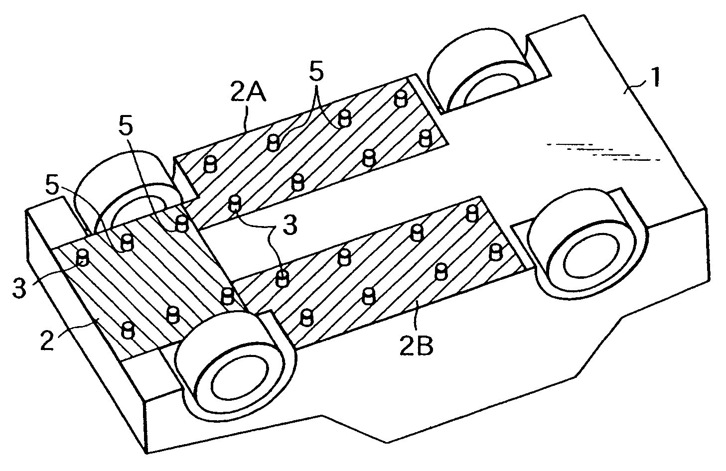
[0043]Embodiments of the present invention will now be described with reference to the drawings. FIG. 1 shows several kinds of undercovers 2, 2A and 2B, more particularly undercover panels, to be attached to the underside 1 of a floor panel of a car body. For attaching the undercovers 2, 2A and 2B to a floor panel, a plurality of studs 3 are fixed to the underside 1 of the floor panel at predetermined positions thereof by welding or the like. The studs 3 may be threaded studs having a threaded portion formed in the outer peripheral surface or may be grooved studs having a groove formed in the outer peripheral surface. In the described embodiments, threaded studs are employed for convenience.

[0044]A plurality of mounting holes 5 are formed in the undercovers 2, 2A and 2B at predetermined positions in conformity with the respective positions of the studs 3 to allow the studs to be inserted therethrough. One particular mounting hole used at a reference position of the undercover may ha...


PUM


Abstract

An apparatus and method for attaching an undercover to the underside of a car body floor panel having a plurality of studs, comprises tubular fasteners that are inserted into respective mounting holes of the undercover with diametral clearance and that are engaged with the studs. Each fastener comprises clips coupled to one another and having flanges that exert a predetermined clamping force on the undercover while permitting displacement of the undercover along the floor panel due to thermal deformation.

Description

CROSS REFERENCE TO RELATED APPLICATIONS[0001]This application is a divisional of application Ser. No. 10 / 406,442 filed Apr. 4, 2003 now U.S. Pat. No. 6,824,203. This application also claims the benefit of Japanese Patent Application No. 2002-103469, both incorporated herein by reference.BACKGROUND OF THE INVENTION[0002]The present invention relates to an apparatus and method for attaching an undercover to the underside of a floor panel of a car body. In particular, the present invention relates to an undercover attaching apparatus and method using studs fixed at predetermined positions on the underside of a floor panel of a car body, mounting holes formed in an undercover to receive the respective studs therein, and stud-engaging fasteners attached to the undercover in respective mounting holes.[0003]It is well known to attach an undercover to the underside of a floor panel of a car body, for example, as disclosed in Japanese Utility Model Laid-Open No. 59-129676. In one technique o...

Claims


Application Information

Patent Timeline
Patent Type & Authority Patents(United States)
IPC IPC(8): B60J7/00B62D25/20B62D29/04F16B5/00F16B5/02F16B21/06
CPCB62D29/048B62D25/2072
Inventor KANIE, HIDEKI
Owner NEWFREY
Why Eureka
Try Eureka