
Method of grinding

a grinding method and grinding technology, applied in the field of grinding methods, can solve the problems of unstable deflection of the bended workpiece at each end of the final grinding process, and achieve the effects of preventing the occurrence of easy dispersion of grinding accuracy

Inactive Publication Date: 2006-05-02
TOYODA MASCH WORKS LTD
View PDF7 Cites 16 Cited by
  • Summary
  • Abstract
  • Description
  • Claims
  • Application Information

AI Technical Summary

Benefits of technology

[0008]In view of the previously mentioned circumstances, it is an object of the present invention to provide a grinding method substantially preventing an occurrence of a dispersion of a grinding accuracy.
[0009]It is second object of the present invention to provide a grinding method substantially restraining an occurrence of a dispersion of a grinding accuracy in a grinding having the same contents of a grinding.
[0010]It is third object of the present invention to provide a grinding method being able to set a suitable grinding condition in each grinding process.

Problems solved by technology

Because of the difference of the termination of sequence by each grinding wheel, a deflection of the bended workpiece is not stable at each end of final grinding process.

Method used


Image

  • Method of grinding
  • Method of grinding
  • Method of grinding

Examples


second embodiment

[0040]the present invention will be described referring to FIG. 5 hereinafter. In this embodiment, a grinding by the grinding wheel T1 and a grinding by the other grinding wheel T2 are individually performed by an in-process controller without synchronousness each other. The individual grinding by each grinding wheel T1, T2 is controlled to be transmitted to next grinding process at the end of the coarse grinding, the intermediate grinding and the fine grinding. Referring to FIG. 5, a removable amount of grinding portion by the grinding wheel T1 is set less than a removable amount of grinding portion by the other grinding wheel T2 in the coarse grinding. In the intermediate grinding or the fine grinding in which the velocity of the grinding feed are less than the velocity of the grinding feed in the coarse grinding and a grinding time is longer a grinding time in the coarse grinding, a removable amount of grinding portion by the other grinding wheel T2 in the intermediate grinding o...

third embodiment

[0041]the present invention will be described referring to FIG. 6. A grinding by the grinding wheel T1 and a grinding by the other grinding wheel T2 are controlled individually by an in-process controller without the synchronousness. A removable amount of the grinding portion by said one grinding wheel is set also same to a removable amount by the other grinding wheel T2 in each of the coarse, the intermediate and the fine grinding, a grinding time by the other grinding wheel T2 delays from a grinding time by one grinding wheel T1 so that the grinding by the grinding wheel T1 is terminated prior to the termination by the grinding wheel T2.

fourth embodiment

[0042]the present invention will be described referring to FIG. 7. FIG. 7 shows only an end portion of grinding process and the other portion is the same to previous embodiments. After a termination of a fine grinding by the grinding wheel T1 (see a point a in FIG. 7), the grinding wheel T1 remains to contact with the workpiece without retraction immediately and both wheels are retracted at the same time when a fine grinding by the other grinding wheel T2 is terminated (see a point b). A velocity of the retraction of grinding wheels T1 and T2 are slow speed like a grinding feed speed, after passing a point c the velocity are changed to a normal rapid retraction speed.


PUM

PropertyMeasurementUnit
speedaaaaaaaaaa
velocityaaaaaaaaaa
feed velocityaaaaaaaaaa

Abstract

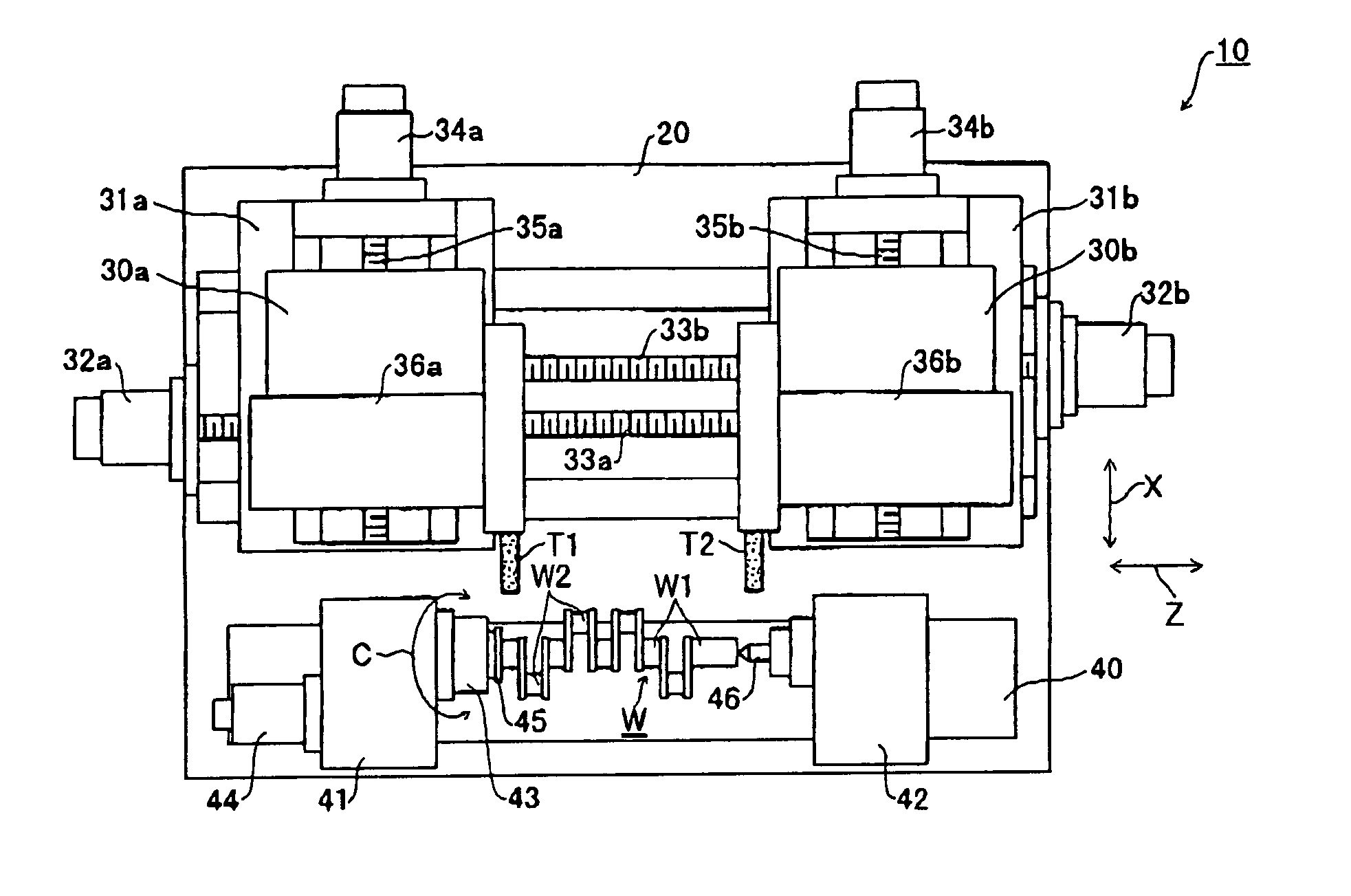
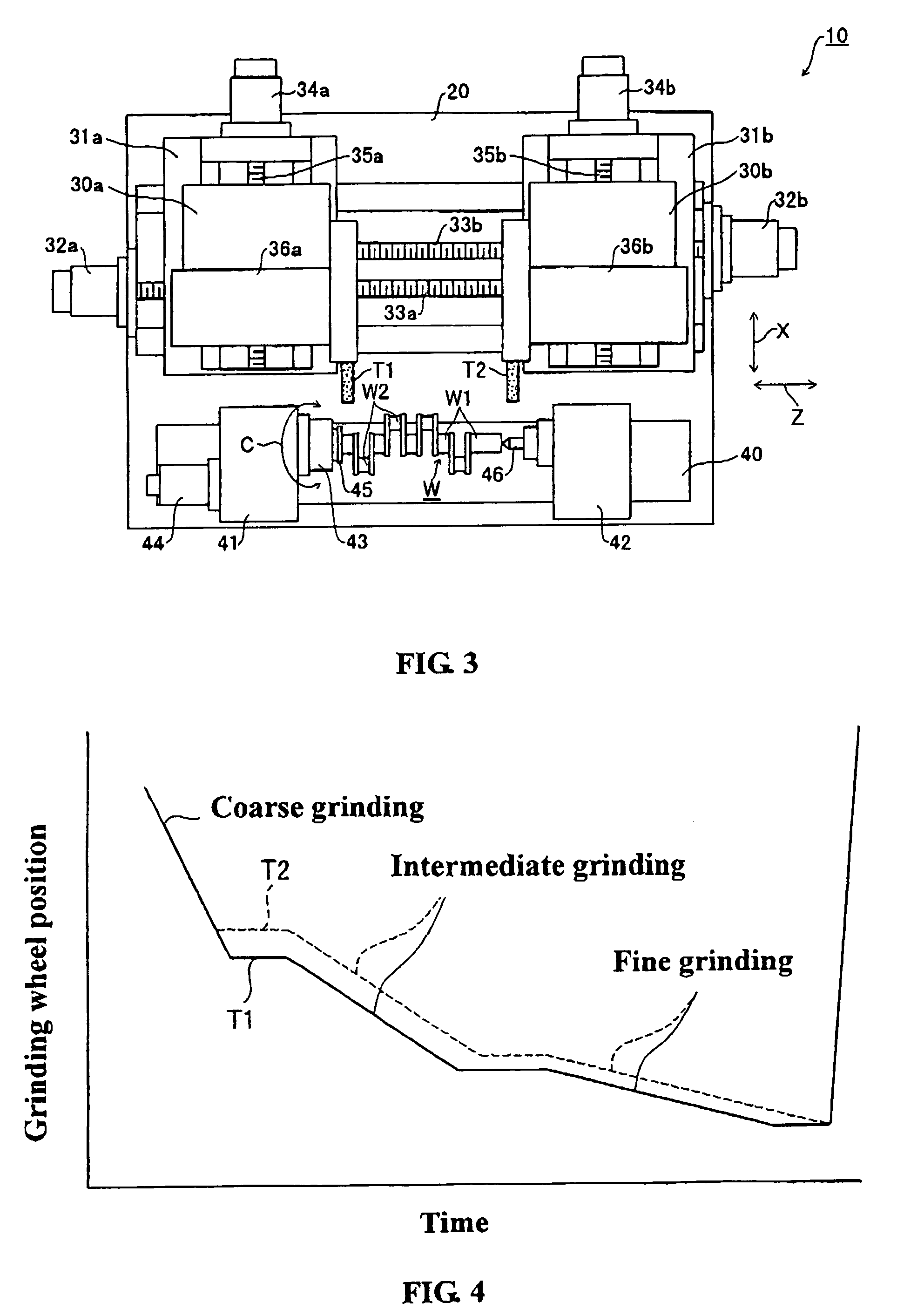
A grinding method comprises steps of simultaneously grinding plural grinding portions of a workpiece by plural grinding wheels T1, T2 moved individually each other, and terminating said grinding by a predetermined grinding wheel T1 prior to a termination of said grinding by the other grinding wheel T2. Whereby, a content of the grinding by each grinding wheel T1, T2 can be same. A grinding condition in each grinding by each grinding wheel T1, T2 can be changed in accordance with a measuring result of the grinding portion in the grinding.

Description

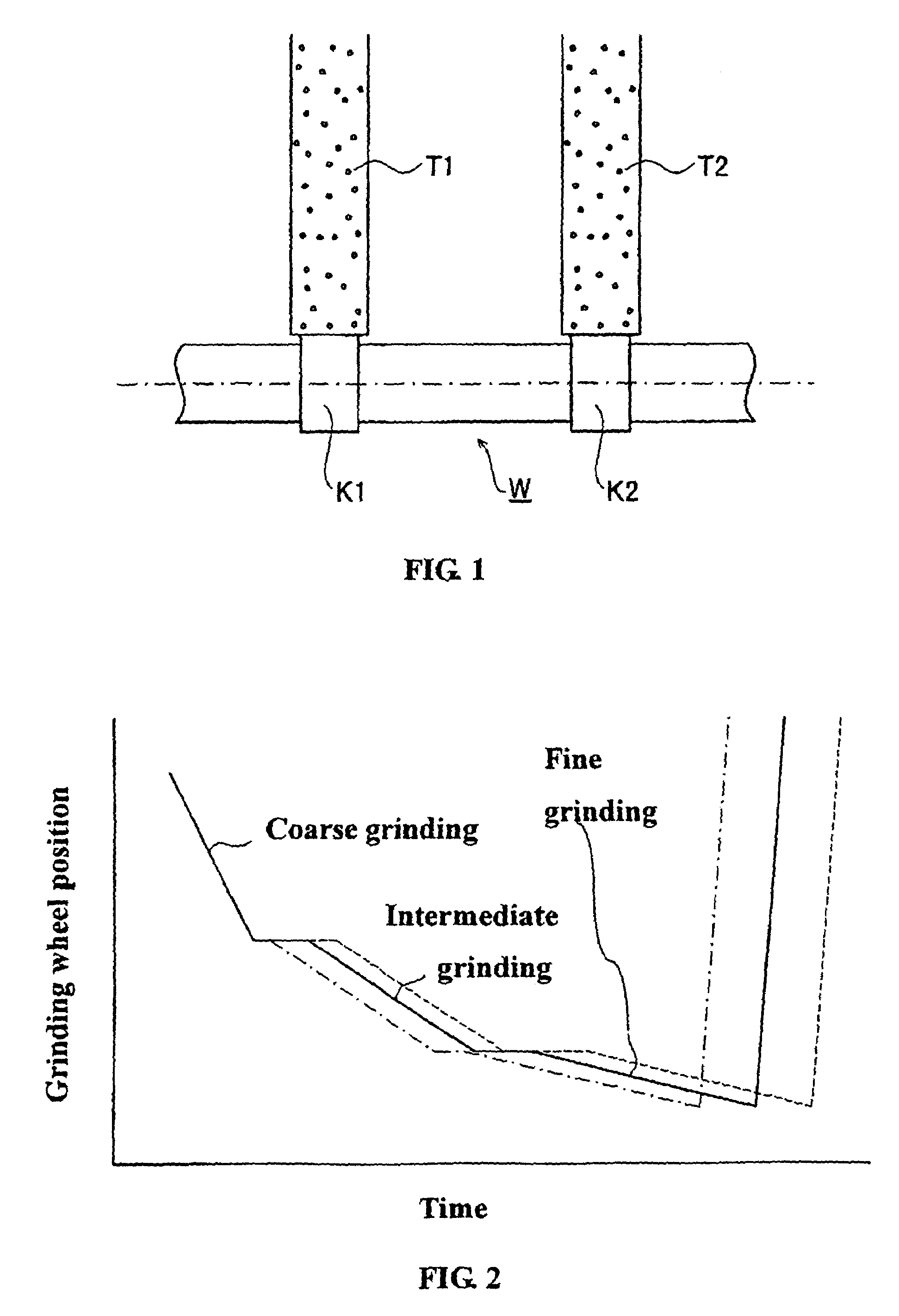
INCORPORATION BY REFERENCE[0001]The present application claims priority under 35 U.S.C. §119 to Japanese Patent Application No. 2002-203642, filed on Jul. 12, 2002. The contents of that application are incorporated herein by reference in their entirety.BACKGROUND OF THE INVENTION[0002]1. Field of the Invention[0003]The invention relates to a grinding method especially for grinding simultaneously plural grinding portions of a workpiece by plural grinding wheels moved individually each other.[0004]2. Description of the Related Art[0005]It is typically known a cylindrical grinding machine having plural grinding wheels individually moved each other to grind simultaneously plural grinding portions of a workpiece. F or example, this technology is disclosed in the U.S. Pat. No. 6,409,573. By the typically known cylindrical grinding machine, as shown in FIG. 1, an individual grinding wheel T1, T2 grinds plural grinding portions K1, K2 of a workpiece W at the same time. Where these kinds of ...

Claims


Application Information

Patent Timeline
Patent Type & Authority Patents(United States)
IPC IPC(8): B24B49/00B24B51/00B23Q15/08B24B5/04B24B5/42B24B17/10B24B19/12B24B27/00
CPCB23Q15/08B24B5/42B24B27/0076B24B17/10G05B2219/45161G05B2219/37367
Inventor NONOYAMA, MAKOTOGOTO, KEITAKURIBAYASHI, MANABU
Owner TOYODA MASCH WORKS LTD
Learn More