Implant device for applying compression across a fracture site

Inactive Publication Date: 2006-05-02
MEDOFF ROBERT J +2
View PDF25 Cites 37 Cited by
  • Summary
  • Abstract
  • Description
  • Claims
  • Application Information

AI Technical Summary

Benefits of technology

[0009]An object of the invention is to provide an implant device which overcomes the above problems and disadvantages by avoidi

Problems solved by technology

One problem with this standard figure 8 tension band wiring occurs because standard large pins A are used which protrude from the end of the bone at F at the location where a major tendon inserts.
Because of this, the ends F of the pins frequentl

Method used


Image

  • Implant device for applying compression across a fracture site
  • Implant device for applying compression across a fracture site
  • Implant device for applying compression across a fracture site

Examples


Embodiment Construction

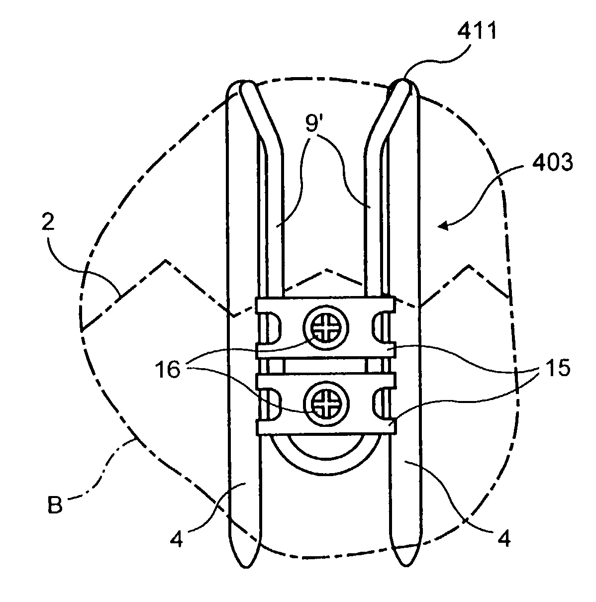
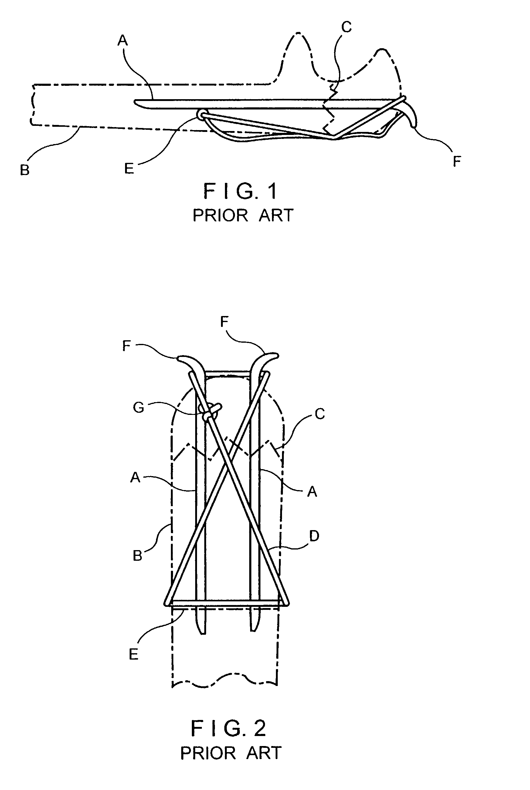
[0055]The drawings illustrate a fracture fixation implant device 1 for applying compression across a fracture 2 in a bone B. The bone B, for example, may be the olecranon or the patella that involve an articular surface.

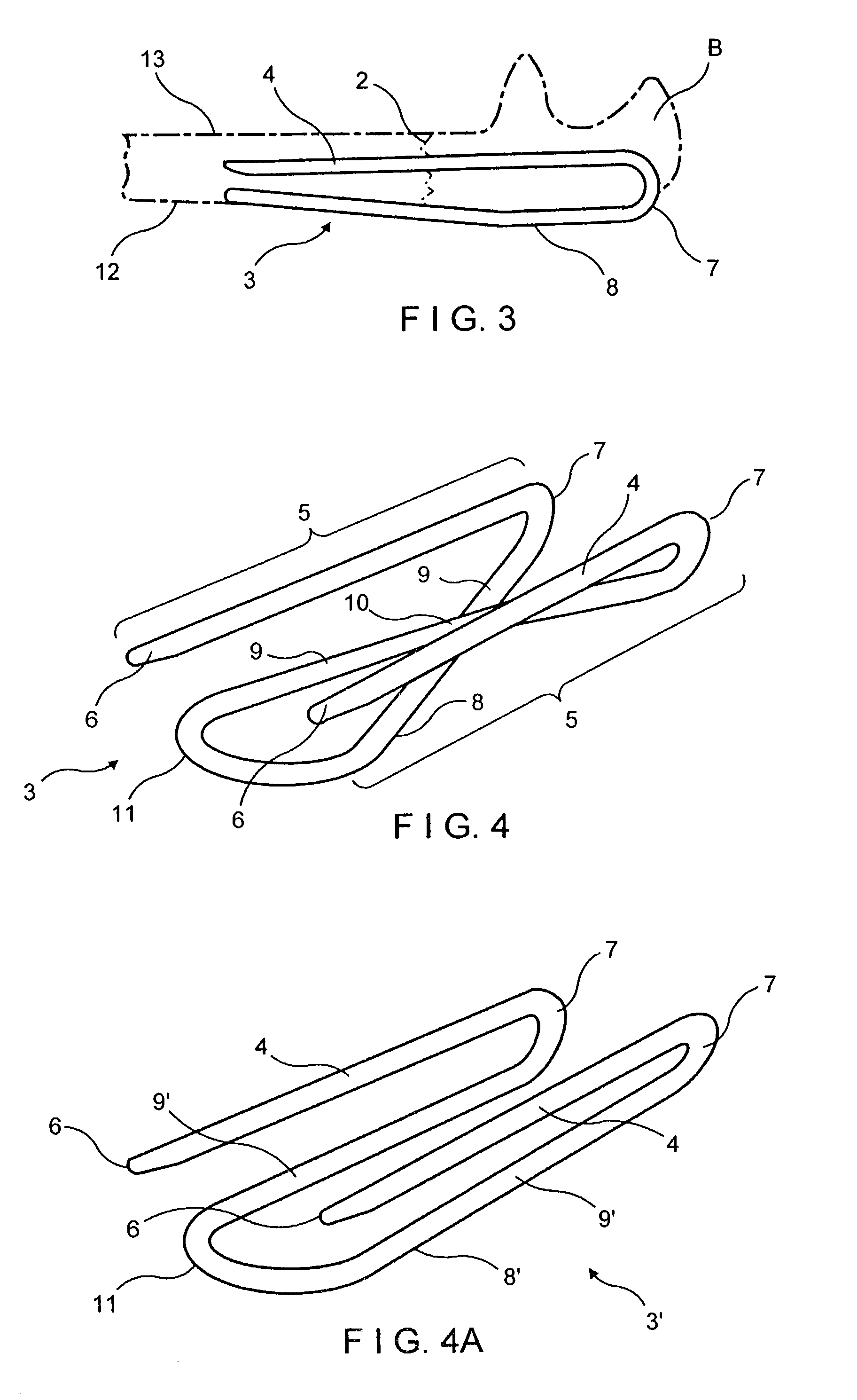
[0056]The implant device 1 comprises a continuous wire element 3 formed with two spaced longitudinally extending legs 4 which are adapted to be driven into the bone B across the fracture 2. The term “wire” or “wire element” is an art recognized term and covers elements having circular or rectangular cross-sections and commonly referred to as pins, wires or bars. The legs 4 form a first portion 5 of the wire element and the legs 4 extend at their ends remote from free ends 6 thereof to bend portions 7 extending outside the bone. Integrally connected to bend portions 7 is a second portion 8 extending backwardly from the bend portions 7 in juxtaposition with the legs 4 of the first portion 5. The second portion 8 includes legs 9 continuous with respective bend portions ...


PUM


Abstract

An implant for applying compression across a fracture site in a bone, the implant comprising a wire element having two spaced adjacent legs adapted to be implanted longitudinally in the bone across the fracture site. The wire element extends outwardly of the bone whereat the legs are bent and extend backwardly into juxtaposition with the legs in the bone and are joined by a U-shaped connecting portion. A tensioning device is engageable with the connecting portion and with a fixation device secured to the bone to apply force to the connection portion and produce tension in the wire element to develop compression across the fracture site.

Description

[0001]“This application claims the benefit of U.S. Provisional Application(s) No(s).: 60 / 268,099 Feb. 12, 2001.FIELD OF THE INVENTION[0002]The invention relates to an implant device for applying compression across a fracture site in a bone and in particular to such an implant device which is constructed as a wire element which is used without separate pins.BACKGROUND AND PRIOR ART[0003]By way of example, fractures of the olecranon (upper end of the ulna at the level of the elbow) and fractures of the patella (kneecap) are fractures that involve an articular surface. Restoration of the joint surface to anatomic alignment is the accepted method of fixation.[0004]Both the olecranon and patella are loaded during joint flexion. The deep articular surface is loaded in longitudinal compression by the reactive forces across the articular surface; the superficial bone surface is loaded in tension by the pull of a strong muscular insertion (the triceps in the case of the olecranon, and the qu...

Claims


Application Information

Patent Timeline
IPC IPC(8): A61B17/56A61B17/58A61B17/68A61B17/88
CPCA61B17/68A61B17/7233A61B17/7208A61B17/8869
Inventor MEDOFF, ROBERT J.
Owner MEDOFF ROBERT J
Why Eureka
Try Eureka