Protection for wind power station

a protection technology for wind power stations, applied in the direction of motors, single-network parallel feeding arrangements, reactive power adjustment/elimination/compensation, etc., can solve the problems of no use of ups systems for power stations and impact on transmission

Inactive Publication Date: 2006-05-02
PILLER GMBH
View PDF14 Cites 31 Cited by
  • Summary
  • Abstract
  • Description
  • Claims
  • Application Information

AI Technical Summary

Benefits of technology

[0005]The protection unit of the new wind power station is no part of an UPS system. There is no use in providing an UPS system for a power station. However, the protection unit at least retards any breakdown of the voltage supplied by the power grip to such an extent that no shock impact on the transmission of the wind power station is caused. For a short time after the breakdown of the voltage provided by the power grid no effect is noticed at the generator at all. The choke decouples the generator from the power grid in such a way that the voltage on the generator side of choke does not drop abruptly. The electrical machine connected to the choke at the same time supplies any reactive power missing from the broken down power grid. Only after the electrical machine slows down the breakdown of the power grid becomes noticeable to the generator but even then not as a sudden drop of the voltage provided. In any case a shock impact on the transmission of the wind power station which is caused by a sudden drop by the voltage at the generator is avoided.
[0012]Additionally, a sensor may be provided for surveying the alternating voltage provided by the power grid on the power grid side of the choke. This sensor can signal a breakdown of the voltage to a control unit controlling the power converters of the generator rotor. The operation of the generator may thus be switched into an emergency mode particularly protecting the transmission of the wind power station against shock impacts. Further, the control may also operate mechanical or electrical breaks which may be provided in the wind power station for any of the rotating parts.
[0016]In another aspect, the present invention relates to a protection unit for a wind power station comprising a wind rotor including at least one blade mounted to a rotatable shaft; a transmission having an input shaft mechanically coupled to the rotatable shaft for rotation therewith at a variable input speed, and an output shaft rotating at a variable output speed which is increased at a fixed ratio as compared to the input speed; and an asynchronous double fed three phase generator having a generator rotor mechanically coupled to the output shaft of the transmission for rotation therewith and electrically coupled to a three phase power grid via at least one power converter per phase of the power grid, and a generator stator electrically coupled to a power grid which provides a rotary voltage having a grid frequency to the generator, the generator supplying a rotary current to the power grid at the grid frequency; wherein the protection unit protects the generator, the power converters and the transmission against accidental breakdowns of the rotary voltage provided by the power grid, and includes one choke per phase of the power grid electrically arranged between the power grid on the one hand, and the generator stator and at least one of the power converters of the generator rotor on the other hand, and a three phase synchronous electrical machine electrically coupled to the chokes.

Problems solved by technology

There is no use in providing an UPS system for a power station.
The shock impact on the transmission because of a sudden drop of the voltage as at the generator is a particular problem with asynchronous double fed generators in which the voltage drop is directly noticed at the generator stator but only through the converters at the generator rotor.

Method used


Image

  • Protection for wind power station
  • Protection for wind power station
  • Protection for wind power station

Examples


Embodiment Construction

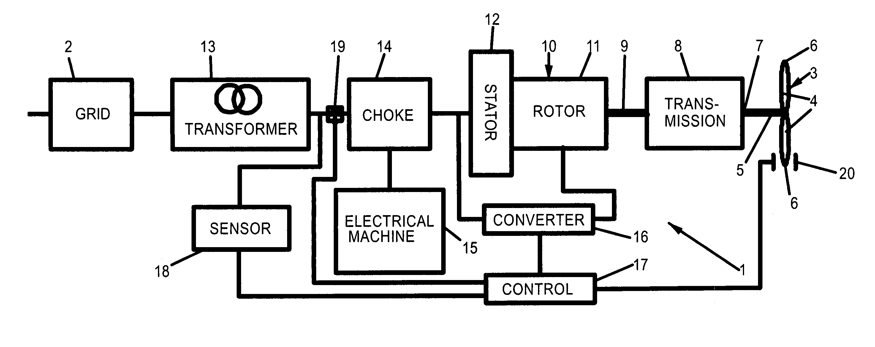
[0023]Referring now in greater detail to the drawings, FIG. 1 illustrates a wind power station 1 connected to a power grid 2. The wind power station 1 includes a wind rotor 3 having at least one, typically 2 or 3 blades 4, each of which being connected to a rotatable shaft 5. Generally, the rotatable shaft 5 is oriented horizontally at a distance to the ground which is in the order of the diameter of the wind rotor 3. Thus, the tips 6 of the blades 4 keep a distance to the ground of about half of the diameter of the wind rotor 3. The rotatable shaft 5 of the wind rotor 3 is mechanically coupled to an input shaft 7 of a transmission 8. The transmission 8 is a fixed ratio transmission increasing the rotational speed of its input shaft 7 into a higher output speed of its output shaft 9. In this way the rotational speed of the wind rotor 3 is raised into an operation range of a generator 10, a rotor 11 of which is mechanically coupled to the output shaft 9 of the transmission for rotati...


PUM


Abstract

A wind power station comprises a wind rotor; a transmission mechanically coupled to the wind rotor; an asynchronous generator having a generator rotor mechanically coupled to the transmission, and a generator stator electrically coupled to a power grid; and a protection unit protecting the generator and the transmission against accidental breakdowns of an alternating voltage provided by the power grid. The Protection unit includes at least one choke electrically arranged between the power grid and the generator stator, and a synchronous electrical machine electrically coupled to the choke.

Description

FIELD OF THE INVENTION[0001]The present invention generally relates to wind power stations. Particularly, the present invention relates to wind power stations comprising a transmission and an asynchronous generator. More particularly, the present invention relates to wind power stations comprising a transmission and an asynchronous double fed generator. Even more particularly, the present invention relates to a protection unit protecting the generator and the transmission of a wind station against accidental breakdowns of a power grid to which the generator is coupled electrically.BACKGROUND OF THE INVENTION[0002]In a wind power station, a wind rotor driven by wind rotates the rotor of a generator to produce electrical energy which is supplied to a power grid. A rotational speed of the wind rotor generally changes with different wind conditions. Further, the speed of the wind rotor is typically much lower than a suitable operation speed of the generator. One known way to cope with t...

Claims


Application Information

Patent Timeline
Patent Type & Authority Patents(United States)
IPC IPC(8): H02P9/10H02P9/14F03D9/00H02J3/18H02J3/38H02P9/04
CPCF03D9/003F05B2270/1071Y02E10/763H02J3/386Y02E10/72F03D9/255H02J2300/28H02J3/381Y02E10/76H02J3/40H02J3/50
Inventor ROSEBROCK, BERNDDARRELMANN, HILMARSCHRADER-HAUSMANN, UWEENGELHARDT, REINHARDSEIDEL, DETLEVKLAUENBERG, ARMINUEFFING, NORBERT
Owner PILLER GMBH
Why Eureka
Try Eureka