System and method for redundant power supply connection

a power supply and system technology, applied in the field of system for connecting redundant power supplies, can solve the problems of reducing the global efficiency of the circuit, damage to the power supply, and the device is therefore not able to limit the current variation at the receiver, so as to reduce the transient over voltage and fast current variation

Inactive Publication Date: 2006-05-02
IBM CORP
View PDF8 Cites 35 Cited by
  • Summary
  • Abstract
  • Description
  • Claims
  • Application Information

AI Technical Summary

Benefits of technology

[0010]In a third embodiment of the invention, the isolation switches are turned off gradually by a disconnection arrangement receiving a sensing signal issued from the receiver that is being unplugged while the power terminals are stil...

Problems solved by technology

However, because of the voltage drop across the diode in its forward conducting direction, these diodes reduce the global efficiency of the circuit.
The MOSFET device provides a conduction p...

Method used


Image

  • System and method for redundant power supply connection
  • System and method for redundant power supply connection
  • System and method for redundant power supply connection

Examples


second embodiment

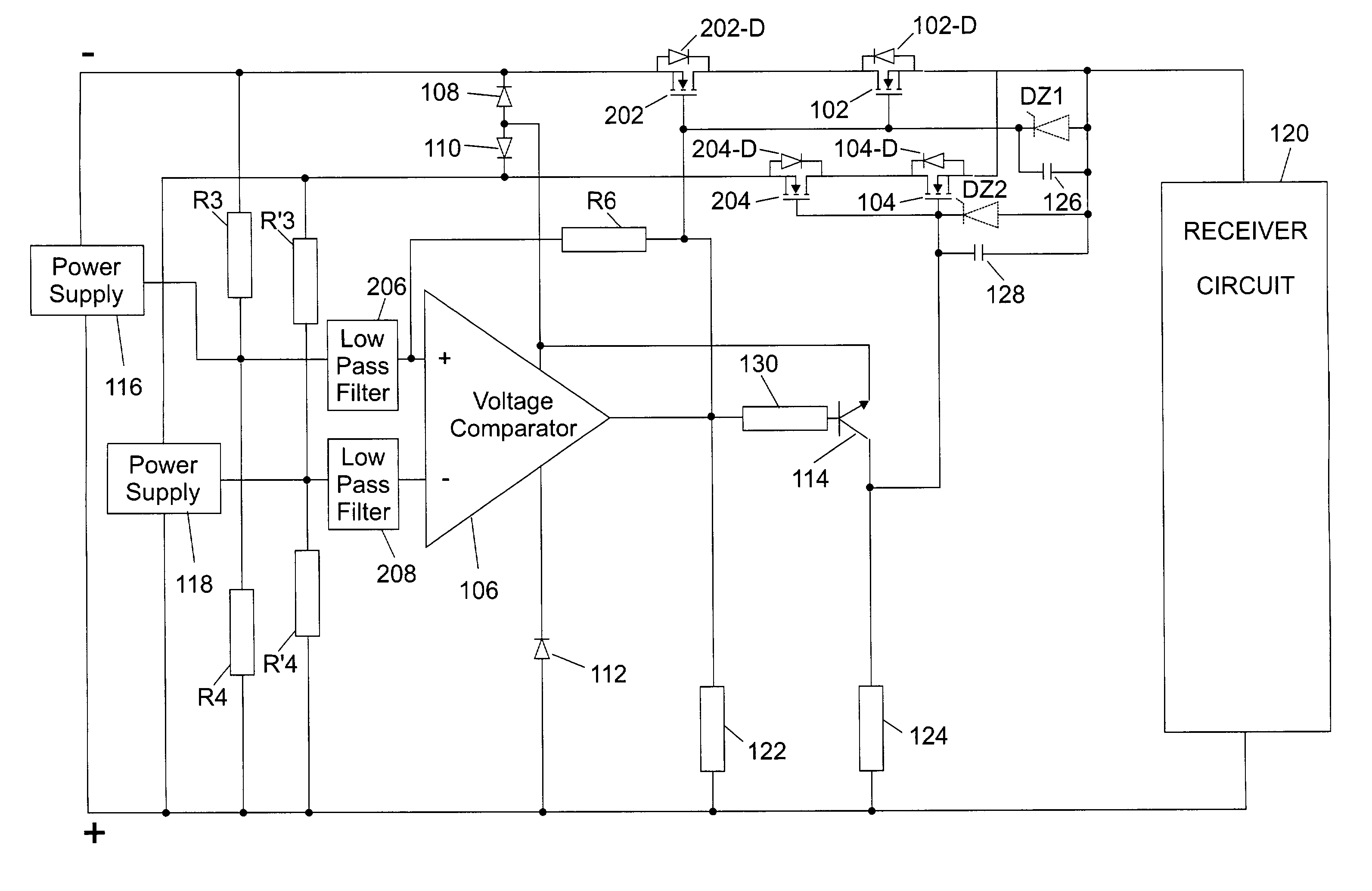
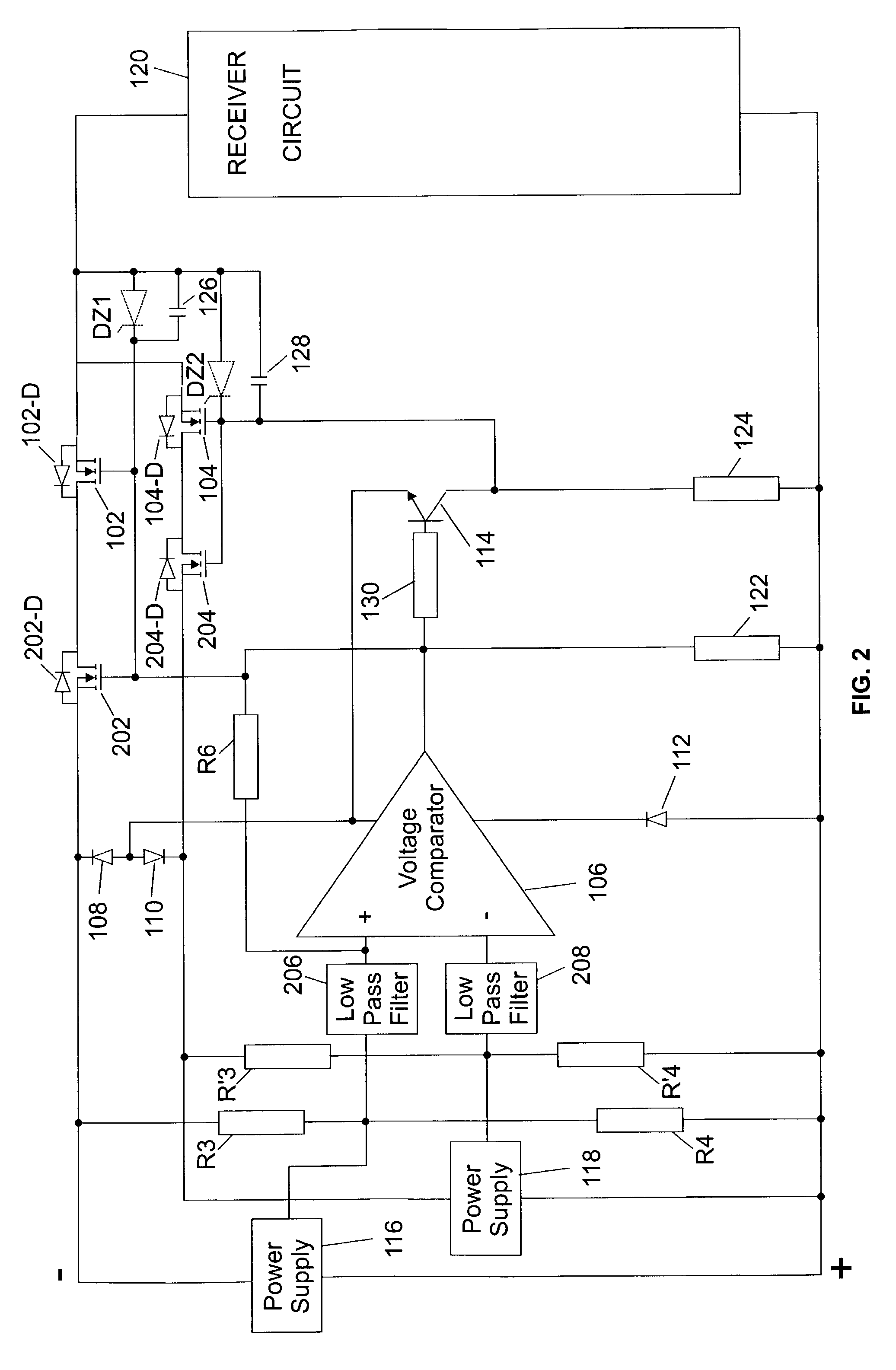
[0032]Referring now to FIG. 2, the invention is described. For ease of description, the same elements shown in FIG. 1 are referenced by the same numbers and only new elements have new references. FIG. 2 illustrates a redundant power supply switching system having four transistor switches 102, 104, 202 and 204, made of the already described first and second control switches 102 and 104 and of first and second isolation switches 202 and 204. In a preferred embodiment, a low pass filter (206,208) is connected at each input of the voltage comparator 106 to limit the number of switchings at the comparator's output, thereby limiting the transistors' switchings.

[0033]The switches are preferably four N-channel MOSFET transistors. The source electrode of first isolation switch 202 is connected to the low voltage terminal of first power supply 116 while the source electrode of second isolation switch 204 is connected to the low voltage terminal of second power supply 118. The drain electrode ...

third embodiment

[0041]Referring now to FIG. 3, a block diagram of the present invention is described. Again, the same reference numbers are applied to common elements between FIGS. 1, 2 and 3 and new numbers reference only new elements. FIG. 3 illustrates the case where the receiver is disconnected from the power supply. A disconnection line is added to the respective gates of first and second isolation switches 202 and 204. A sensor circuit 302 is coupled to the receiver to provide a sensing signal when the receiver starts to be unplugged while its supply input terminals are still in contact with at least both terminals of first or second power supply 116 or 118.

[0042]The output of the sensor drives the base of two disconnection transistors 304 and 306. Both emitters of transistors 304 and 306 are connected to the lowest terminal of first or second power supplies 116 or 118 through the arrangement of diodes 108 and 110. In a preferred embodiment, a first resistor R7 is connected between the output...


PUM


Abstract

A system for connecting a receiver to a redundant power supply. The power supply units are connected to the receiver by means of a pair of control switches, each being connected in series between one of the power units and the receiver, and each having its intrinsic diode forwardly biased between the power unit and the receiver. A voltage comparator senses which of the power supply units is having the higher potential difference between its high and low potential terminals. The output of the comparator controls the gate of both control switches such that the control switch in series with the sensed power supply unit is conducting while the other one is off. When a reversed polarity is applied to the receiver, the receiver is protected by the intrinsic diode. When at least one of the power supplies is connected with the correct polarity, the receiver is supplied without an appreciable voltage drop and with the lowest possible power losses.

Description

FIELD OF THE INVENTION[0001]The present invention relates to a system for connecting redundant power supplies.BACKGROUND OF THE INVENTION[0002]Current sources which are non-interruptible commonly have two redundant D.C. power sources connected by means of relay or solid state switches to a single receiver. If one of the power supplies fail, the receiver can be carried out by the other power supply. In many applications where redundant power supplies are used, it is desirable to protect the receiver against reversed polarity of the power supply. Moreover, it is also desirable to dynamically switch the receiver from one power supply to the other, and to limit the current variation when the receiver is being connected to the power supply or being disconnected from it.[0003]Typical redundant power supply solutions commonly use a forward biased diode per power supply in one or both of the higher and lower potential lines. These diodes serve to avoid short circuits between power supplies ...

Claims


Application Information

Patent Timeline
IPC IPC(8): H03K17/00H02J1/08H02J9/06
CPCH02J9/061H02J1/08
Inventor FAUH, JEAN-FRANCOISFONTEBRIDE, ARNAULTROMAN, DENIS
Owner IBM CORP
Why Eureka
Try Eureka