
Kit of parts for assembling an optical element, method of assembling an optical element, optical element, lithographic apparatus, and device manufacturing method

a technology of parts and components, applied in the field of parts and components for assembling an optical element, can solve the problems of increasing the cost of ownership, undesirable use of spatial filters, and increasing the throughput of the apparatus, and achieve the effect of quick and inexpensive assembly

Inactive Publication Date: 2006-05-02
ASML NETHERLANDS BV
View PDF14 Cites 83 Cited by
  • Summary
  • Abstract
  • Description
  • Claims
  • Application Information

AI Technical Summary

Benefits of technology

The present invention provides an optical element that can be quickly and easily assembled to create the desired illumination mode for a lithographic apparatus. The optical element is made up of a plurality of previously manufactured optical components that are assembled into an array on a holder. The optical components can redirect, effect, or transform the incident radiation in a way that is specific to the mask pattern being used. The optical element can be made from diffractive, refractive, or reflective optical components, and can be designed to create a specific illumination mode. The optical elements can be reused for different mask patterns and can be easily assembled using the provided kit of parts.

Problems solved by technology

Using spatial filters is undesirable because the resulting loss of light reduces the throughput of the apparatus and hence increases its cost of ownership.
Arrangements with bundles of optical fibers are complex and inflexible.
However, in practice it takes many months to manufacture a diffractive optical element so that it is impractical in most cases.

Method used


Image

  • Kit of parts for assembling an optical element, method of assembling an optical element, optical element, lithographic apparatus, and device manufacturing method
  • Kit of parts for assembling an optical element, method of assembling an optical element, optical element, lithographic apparatus, and device manufacturing method
  • Kit of parts for assembling an optical element, method of assembling an optical element, optical element, lithographic apparatus, and device manufacturing method

Examples


second embodiment

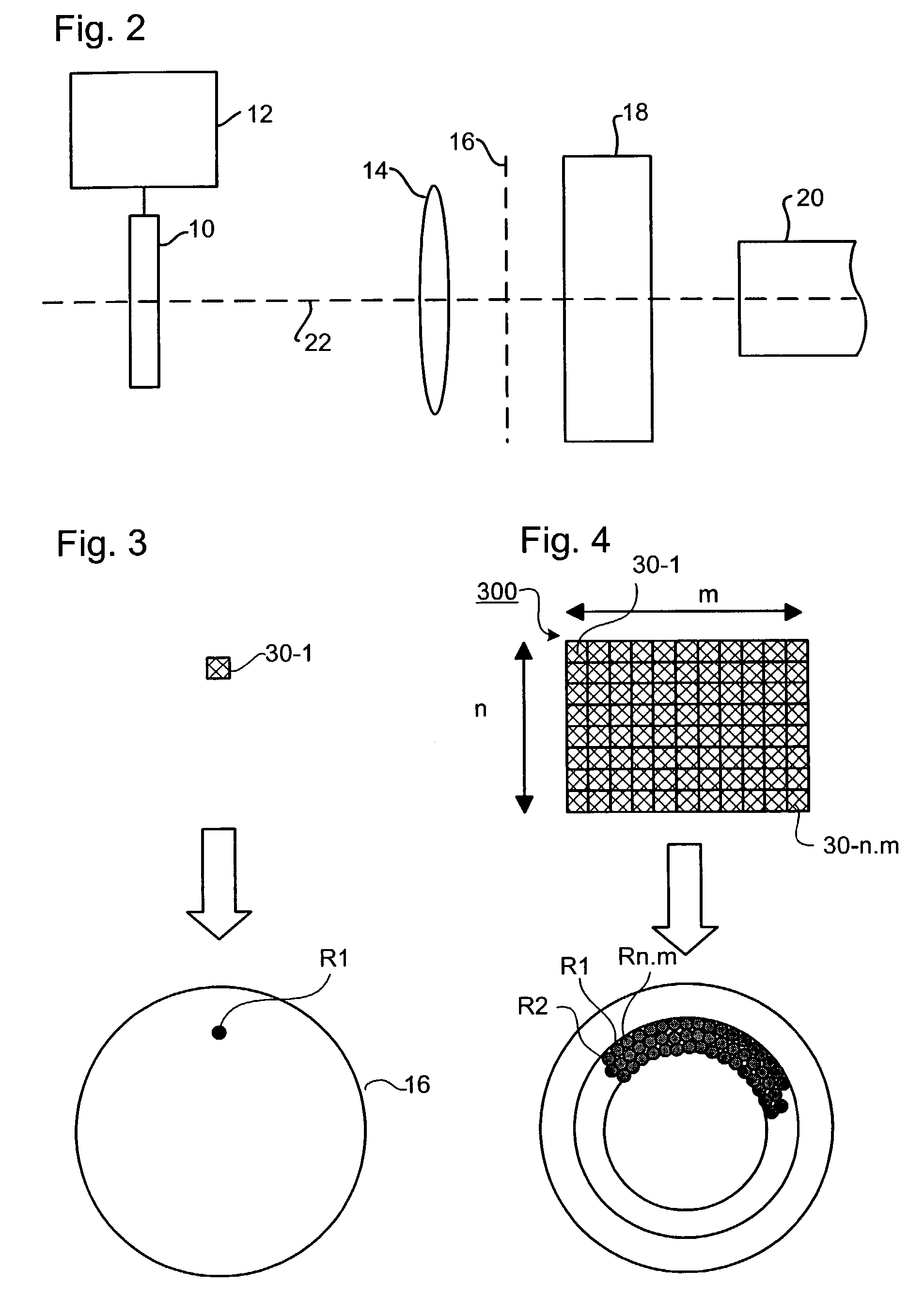
[0069]FIG. 8 illustrates an optical element 500 according to the invention. It is essentially the same as the optical element 300 but includes polarization changing components 50, such as for example half lambda plates, arranged in various orientations as desired to control the polarization of the illumination beam. According to their orientations, the polarization changing components 50 rotate the polarization state of a polarized projection beam PB, which may, for example, be generated by an excimer laser. Thus the relative intensities of different polarization states in the beam can be controlled, as can the distribution of polarization in the pupil, due to the combined action of the polarization changing components 50 and on top of them the optical components 30 which redirect the radiation. It may be appreciated that, although FIG. 8 shows an example of an optical element made of two layers of optical components, a third or fourth layer of optical components might be added to t...

third embodiment

[0077]In the third embodiment, the optical element 400 comprises a plate-like optical element 41 that directs incident radiation from the beam PB into a narrow range of angles. The plate-like element may be a diffractive, refractive, or diffusive optical element, e.g. a diffusor plate. On the output side an array of wedges 42-1 to 42-n.m are provided; these may also be placed on the input side if preferred. The wedges 42-1 to 42-n.m have differing wedge angles and so emit narrow cones of radiation 43-1, 43-2 at differing angles. The differing angles of the cones translate into different regions of the pupil plane 16.

[0078]The third embodiment may be advantageous as compared to the first in that wedges can be manufactured more cheaply than, for example, different diffractive optical components 30. The wedges can simply be placed on the plate-like element 41 and held in place by gravity or held between element 41 and a second plate-like element. The second plate-like element may have ...


PUM

PropertyMeasurementUnit
wavelengthaaaaaaaaaa

Abstract

A kit of parts for assembling an optical element for use in a lithographic apparatus includes a large number of different small pieces which direct light into respective regions of the pupil plane of the radiation system and / or change the polarization state of incident radiation. The previously manufactured pieces arc selected and assembled into an optical element to rapidly create a desired intensity distribution. The optical element may also be disassembled and the pieces reused.

Description

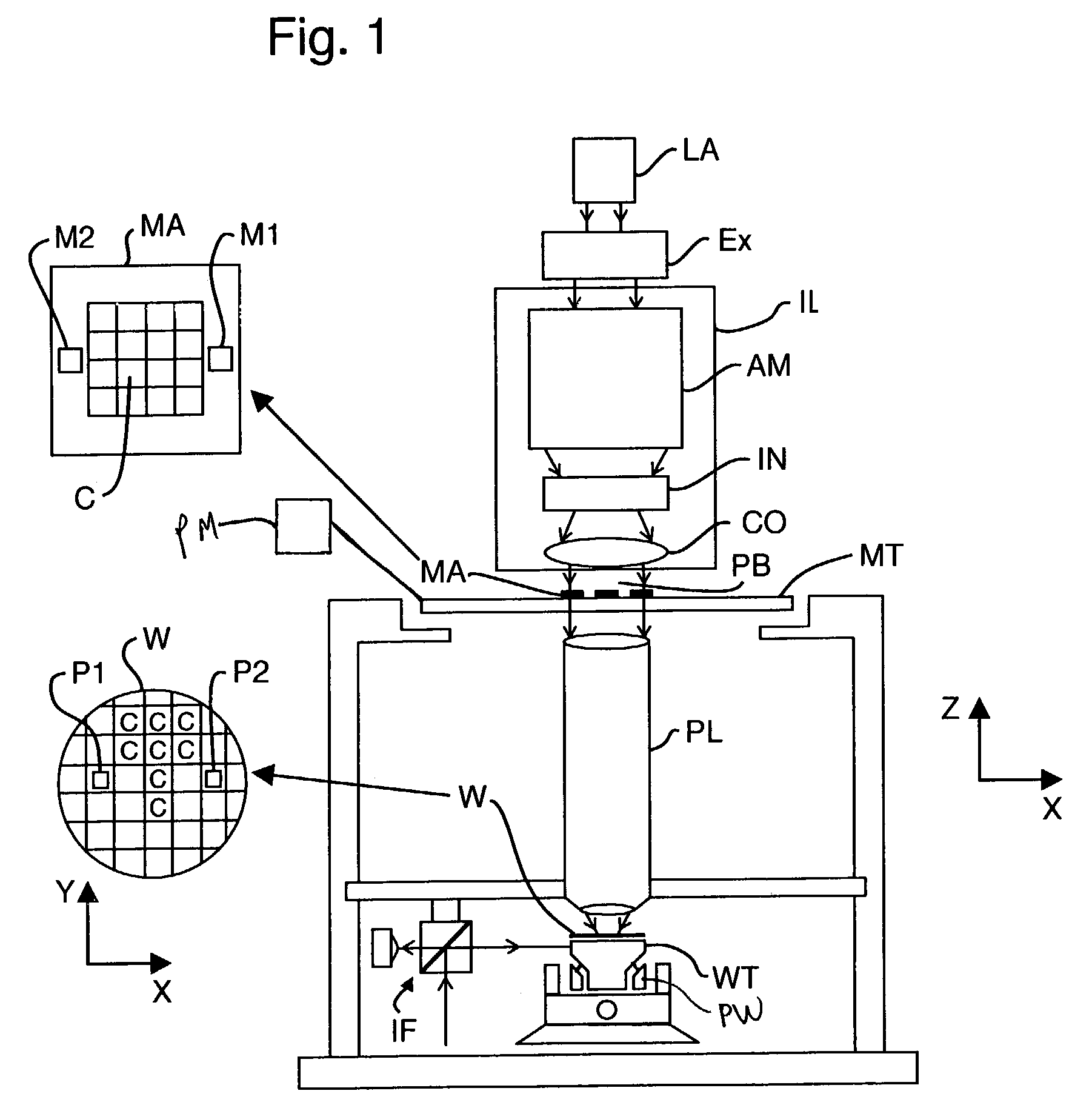
[0001]This application claims priority to European Applications 02258349.6, filed Dec. 3, 2002, and 02253851.6, filed May 31, 2002, which are incorporated in their entirety by reference herein.BACKGROUND OF THE INVENTION[0002]1. Field of the Invention[0003]The present invention relates to the assembly of optical elements for effecting a desired change in incident radiation to be used in a lithographic apparatus.[0004]2. Description of the Related Art[0005]The term “patterning device” as here employed should be broadly interpreted as referring to device that can be used to endow an incoming radiation beam with a patterned cross-section, corresponding to a pattern that is to be created in a target portion of the substrate. The term “light valve” can also be used in this context. Generally, the pattern will correspond to a particular functional layer in a device being created in the target portion, such as an integrated circuit or other device (see below). An example of such a patterni...

Claims


Application Information

Patent Timeline
Patent Type & Authority Patents(United States)
IPC IPC(8): G03B27/54G02B7/02G03B27/42G02B7/00G02B19/00G03F7/20H01L21/027
CPCG03F7/70075G03F7/70108G03F7/70825G03F7/70566G03F7/70158H01L21/027
Inventor MULDER, HEINE MELLEVAN GREEVENBROEK, HENDRIKUS ROBERTUS MARIE
Owner ASML NETHERLANDS BV
Learn More