
Moving image packet decoding and reproducing apparatus, reproduction time control method thereof, computer program product for controlling reproduction time and multimedia information receiving apparatus

Inactive Publication Date: 2006-05-02
KK TOSHIBA
View PDF13 Cites 66 Cited by
  • Summary
  • Abstract
  • Description
  • Claims
  • Application Information

AI Technical Summary

Benefits of technology

[0013]Therefore, it is the object of the present invention to provide a reproduction time control method adapted to correct time stamp information when one or more than one error occurs in the time stamp information to be used for synchronizing the reproduction of a moving image and a corresponding sound realized by demultiplexing the signal of the moving image and that of the corresponding sound in the multimedia information obtained by multiplexing the bit stream of the moving image and that of the sound, a computer program product for realizing the method, a moving image decoding and reproducing apparatus that can reliably synchronize the moving image signal and the audio signal through the processing operation of the program product and a multimedia information receiving apparatus comprising such a moving image decoding and reproducing apparatus.

Problems solved by technology

In other words, it is not conceivable that errors are contained in time stamp information.
However, in the case of data transmission systems and mobile telephone systems comprising mobile communication terminals where the transmission bit rate is low, it is not allowable to assign a wide band to the feature of correcting errors in the system data area including time stamps.
Furthermore, when multimedia contents are transmitted on a real time basis by radio transmission, measures not involving retransmission will more often than not be taken as in the case of UDP (User Datagram Protocol), although errors due to radio transmission may additionally be involved.
Then, it is probable that errors frequently occur in time stamps.
Particularly, since the volume of data of a moving image is large, errors can occur in the time stamps in the moving image signal.

Method used


Image

  • Moving image packet decoding and reproducing apparatus, reproduction time control method thereof, computer program product for controlling reproduction time and multimedia information receiving apparatus
  • Moving image packet decoding and reproducing apparatus, reproduction time control method thereof, computer program product for controlling reproduction time and multimedia information receiving apparatus
  • Moving image packet decoding and reproducing apparatus, reproduction time control method thereof, computer program product for controlling reproduction time and multimedia information receiving apparatus

Examples


Embodiment Construction

[0041]Now, the present invention will be described in greater detail by referring to the accompanying drawings that illustrate preferred embodiments of the invention.

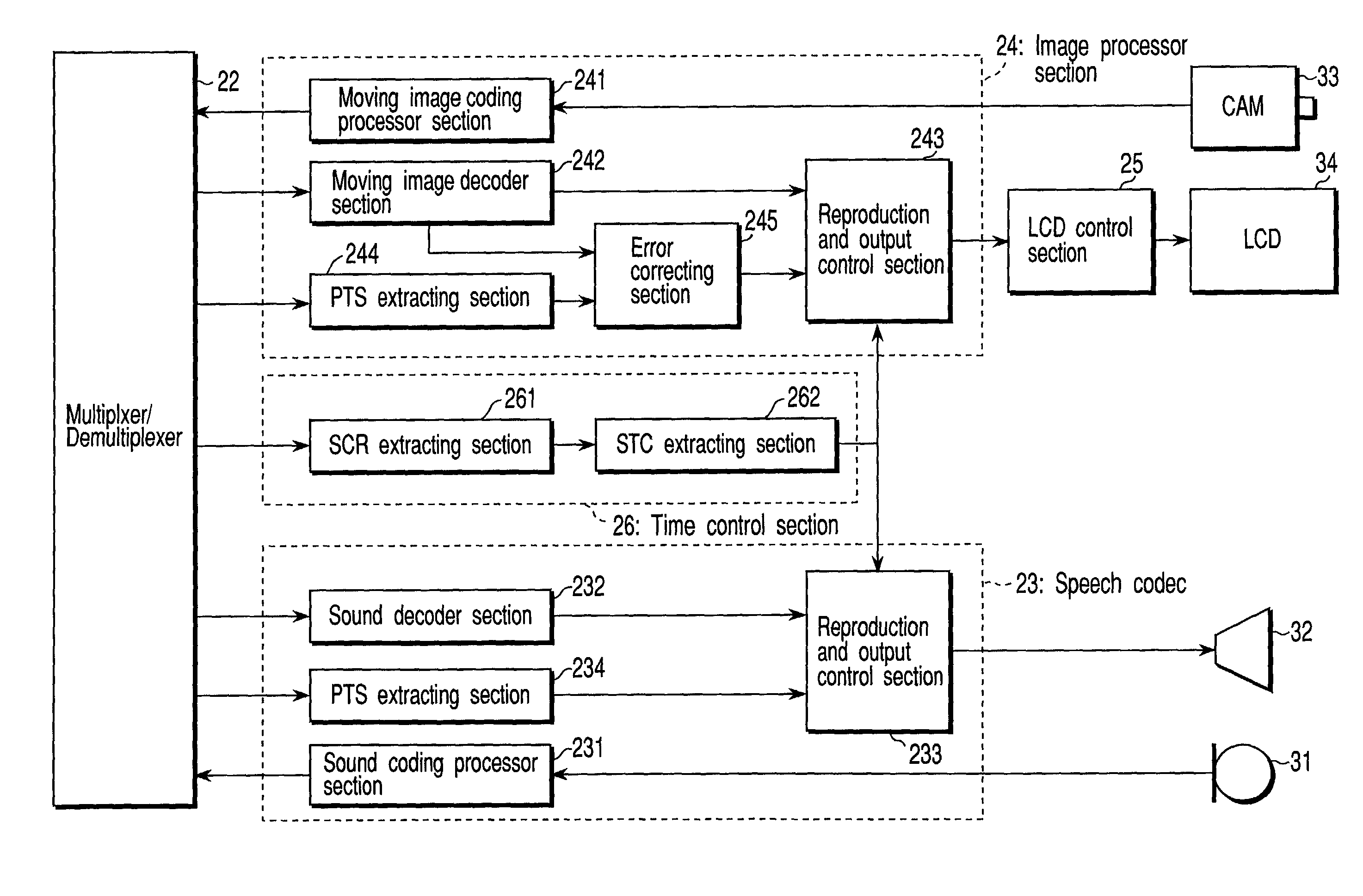
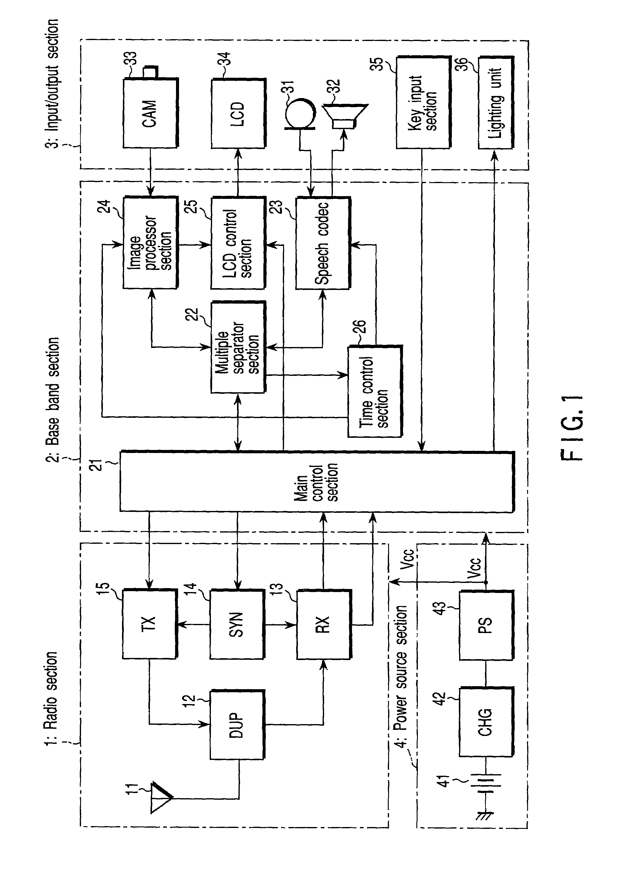
[0042]FIG. 1 is a schematic block diagram of an embodiment of a multimedia information receiving apparatus according to the invention as applied to a mobile communication terminal such as cellular telephone, illustrating its entire configuration. The mobile communication terminal MS shown in FIG. 1 comprises a radio section 1, a base band section 2, an input and output section 3 and a power source section 4.

[0043]Referring to FIG. 1, the radio frequency signal arriving from a base station (not shown) by way of a radio line of a mobile communication system is received by antenna 11 and input to reception circuit (RX) 13 by way of an antenna duplexer (DUP) 12. The reception circuit 13 comprises a high frequency amplifier, a frequency converter and a demodulator. The received radio frequency signal is subjected to low nois...


PUM


Abstract

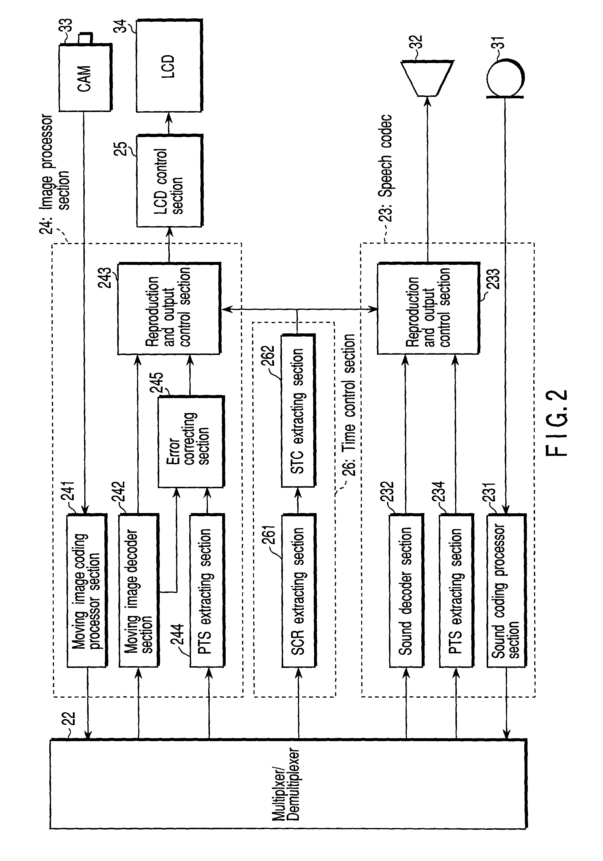
Error correcting section holds PTS(n−1) and DTS(n−1) of the frame immediately preceding the current frame and the most recent CPTS as determined to be correct in the past. The time stamp of the current frame is determined to be incorrect if (1) CPTS>PTS(n) which is the current frame or (2) CPTS<PTS(n) and greater than the time interval of time information B_TS(n)−B_TS(n−1) plus a reference time (e.g., the multiple of the standard frame interval 33 msec of moving images using 30 frames per second). If the PTS(n) of the current frame is correct, it is used as reproduction timing and updates the CPTS, using the PTS(n). If, on the other hand, the PTS(n) of the current frame is incorrect, it is not used and the time obtained by adding the CPTS and B_TS(n)−B_TS(n−1) is used as corrected PTS(n).

Description

CROSS-REFERENCE TO RELATED APPLICATIONS[0001]This application is based upon and claims the benefit of priority from the prior Japanese Patent Application No. 2000-329266, filed Oct. 27, 2000, the entire contents of which are incorporated herein by reference.BACKGROUND OF THE INVENTION[0002]1. Field of the Invention[0003]This invention relates to a multimedia information receiving apparatus for receiving multimedia information typically prepared by multiplexing an audio signal and a moving image signal that are related to each other and compressed separately, demultiplexing and expanding the audio signal and the moving image signal and reproducing them synchronously. More particularly, the present invention relates to a moving image packet decoding and reproducing apparatus and also to a computer program product for controlling the reproduction time adapted to be used with such an apparatus.[0004]2. Description of the Related Art[0005]Generally, in digital broadcasting, a transmissio...

Claims


Application Information

Patent Timeline
IPC IPC(8): H04J3/06H04N5/04H04N7/00H04J3/00H04N19/44H04N7/52H04N7/62H04N19/00H04N19/65H04N19/70H04N19/89H04N21/2368H04N21/242H04N21/414H04N21/422H04N21/4223H04N21/43H04N21/434
CPCH04N21/2368H04N21/242H04N21/41407H04N21/4341H04N21/4223H04N21/4307H04N21/42203H04N21/43072
Inventor KAWAKATSU, HIROKAZU
Owner KK TOSHIBA
Learn More