Method for digital transmission and display of weather imagery

a technology of digital transmission and weather imagery, applied in the direction of navigation instruments, instruments, using reradiation, etc., can solve the problems of slow link to the aircraft cockpit from a satellite, large weather graphics files, and inability to increase the distance between the radar and the sensor, so as to reduce the bandwidth required for transmitting and achieve high-resolution images.

Inactive Publication Date: 2006-05-02
AVIDYNE CORPORATION
View PDF15 Cites 103 Cited by
  • Summary
  • Abstract
  • Description
  • Claims
  • Application Information

AI Technical Summary

Benefits of technology

[0006]In the present invention, minimal data is created to represent a source image reducing the bandwidth required for transmitting the source image and allowing a high-resolution image to be generated. Minimal data representing a source image is created by first dividin

Problems solved by technology

The airborne weather radar cannot be relied upon at increased distances from the sensor because a radar beam increases in width with increased distance from the sensor.
However, weather graphics files are very large and a link to the aircraft cockpit fr

Method used


Image

  • Method for digital transmission and display of weather imagery
  • Method for digital transmission and display of weather imagery
  • Method for digital transmission and display of weather imagery

Examples


Embodiment Construction

[0024]A description of preferred embodiments of the invention follows.

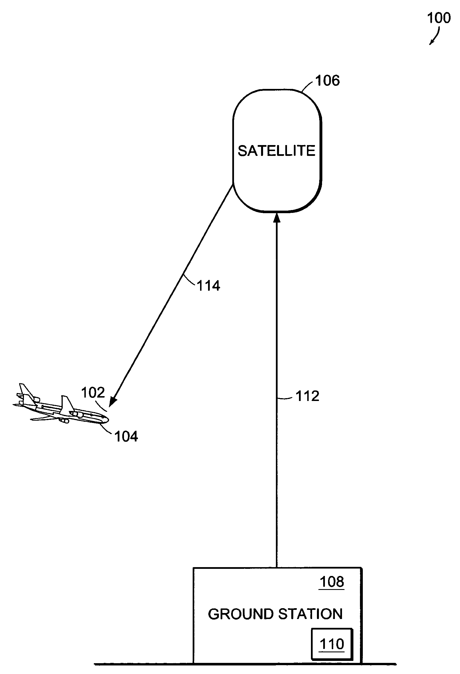
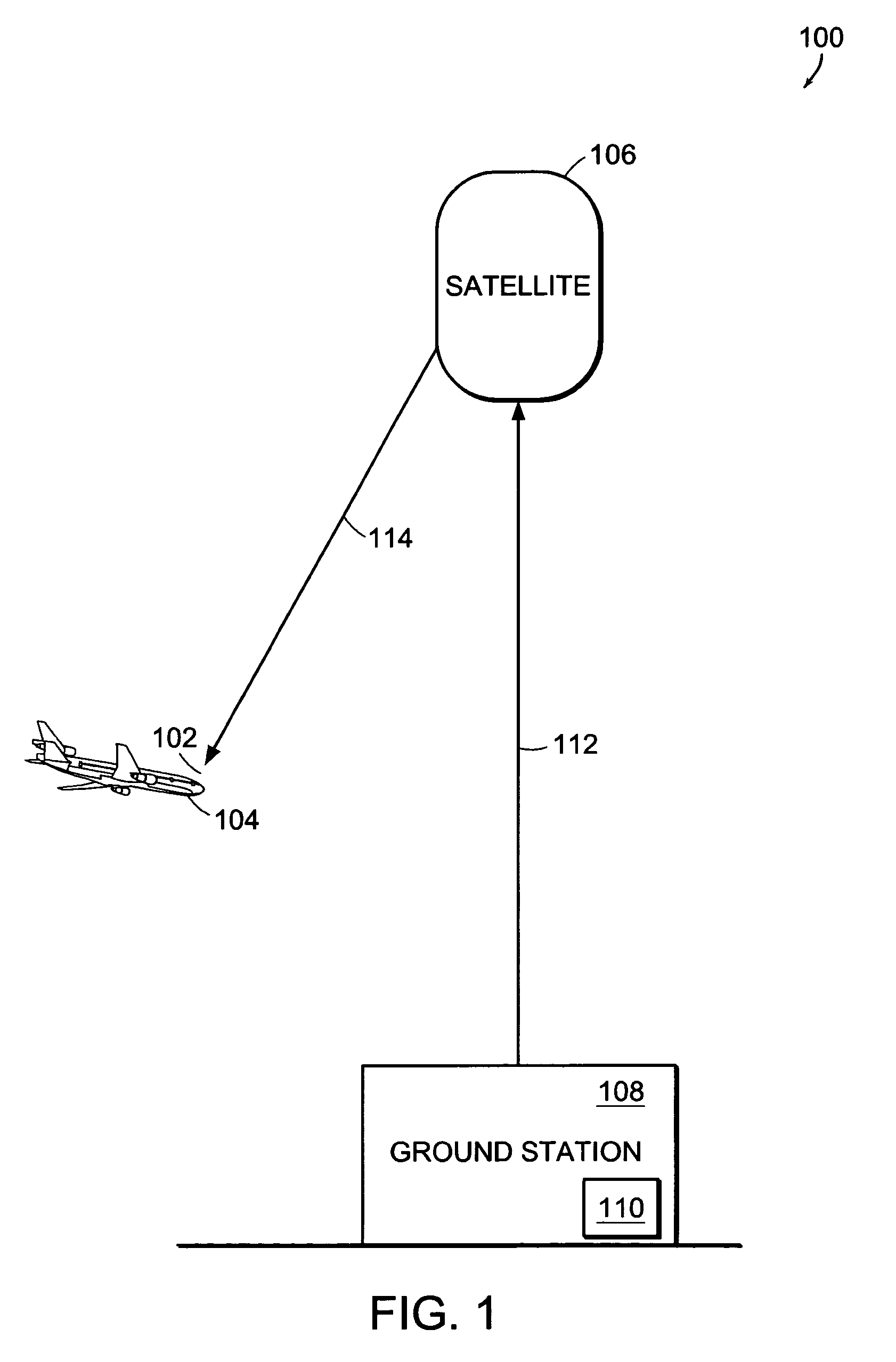
[0025]FIG. 1 illustrates a weather imagery system 100, which compresses a source weather image 110 for uploading to a satellite 106, and a system 104 in the aircraft 102 for reconstruction of the downlinked weather image according to the principles of the present invention. The source weather image 110 is computed based on where the system 100 expects the aircraft 102 to be along a flight plan when it receives the weather image. Thus, the downlinked weather image (over 114) is used for long-range flight planning. Typically, it takes five to ten minutes to download the weather image from a ground station 108 through the satellite 106 to the aircraft 102.

[0026]The system 100 uses a position model to coordinate weather data and the position of the aircraft 102. The aircraft 102 sends position, ground track and ground speed to the ground station 108 so that the aircraft's location can be predicted when the next weathe...


PUM


Abstract

A method for creating minimal data representing a source image is presented. The source image is divided into a grid of cells. A color is selected for each cell corner based on sampling an area defined by the cell corner. An indication of the selected color is stored in an array dependent on the co-ordinates of the cell corner in the source image.

Description

RELATED APPLICATION[0001]This application claims the benefit of U.S. Provisional Application No. 60 / 397,591, filed on Jul. 19, 2002. The entire teachings of the above application are incorporated herein by reference.BACKGROUND OF THE INVENTION[0002]An aircraft pilot needs up to date (timely) information on weather conditions in order to avoid flying through severe weather conditions. Typically, this is provided by displaying weather conditions detected by an airborne weather radar. The weather radar system includes an antenna receiver / transmitter unit attached to the aircraft. The unit emits a concentrated beam of microwave energy. The returned echo indicates the intensity of detected targets. The detected intensity is displayed as color coded targets depicting echoes on a display (i.e. cockpit monitor). The intensity of the rainfall at a given location is indicated by the color displayed. For example, black represents very light or no precipitation, green represents light precipita...

Claims


Application Information

Patent Timeline
IPC IPC(8): G01C23/00
CPCG01S7/003H04N19/94H04N19/186H04N19/17H04N19/119G01S13/951Y02A90/10
Inventor SOUTHARD, DAVID A.BELL, LOWELL F.AUCOIN, MICHAEL A.GOUIN, FREDERICCANNADAY, JR., THEODORE H.
Owner AVIDYNE CORPORATION
Why Eureka
Try Eureka