Drive control apparatus for hybrid vehicle

a hybrid vehicle and control apparatus technology, applied in electric control, road transport, engine starters, etc., can solve the problems of low-voltage battery voltage drop, affecting the operation of the propulsion controller, and affecting the range of the range, so as to reduce fuel consumption and increase the range

Active Publication Date: 2006-05-09
HONDA MOTOR CO LTD
View PDF35 Cites 52 Cited by
  • Summary
  • Abstract
  • Description
  • Claims
  • Application Information

AI Technical Summary

Benefits of technology

[0011]It is therefore an object of the present invention to provide a drive control apparatus for increasing a range in which a hybrid vehicle is propelled by only a motor with an engine being disabled, for thereby reducing fuel consumption.

Problems solved by technology

When a starter motor starts an engine, the starter motor needs to consume a large amount of electric power, causing a voltage drop across a battery that is connected to the starter motor.
Since the low-voltage battery also supplies electric power to a propulsion controller other than the starter motor, when the engine is started, the voltage across the low-voltage battery drops, possibly affecting the operation of the propulsion controller.
Further, with the system disclosed in Japanese patent No. 2,973,797, the engine cannot be started while the hybrid vehicle is running.
Therefore, a speed range in which the hybrid vehicle can travel in the EV mode, i.e., a rotational speed range of the propulsive motor, is relatively narrow, making it difficult for the hybrid vehicle to give its expected performance sufficiently.

Method used


Image

  • Drive control apparatus for hybrid vehicle
  • Drive control apparatus for hybrid vehicle
  • Drive control apparatus for hybrid vehicle

Examples


Embodiment Construction

[0052]A drive control apparatus for a hybrid vehicle according to a preferred embodiment of the present invention will be described below with reference to FIGS. 1 through 17.

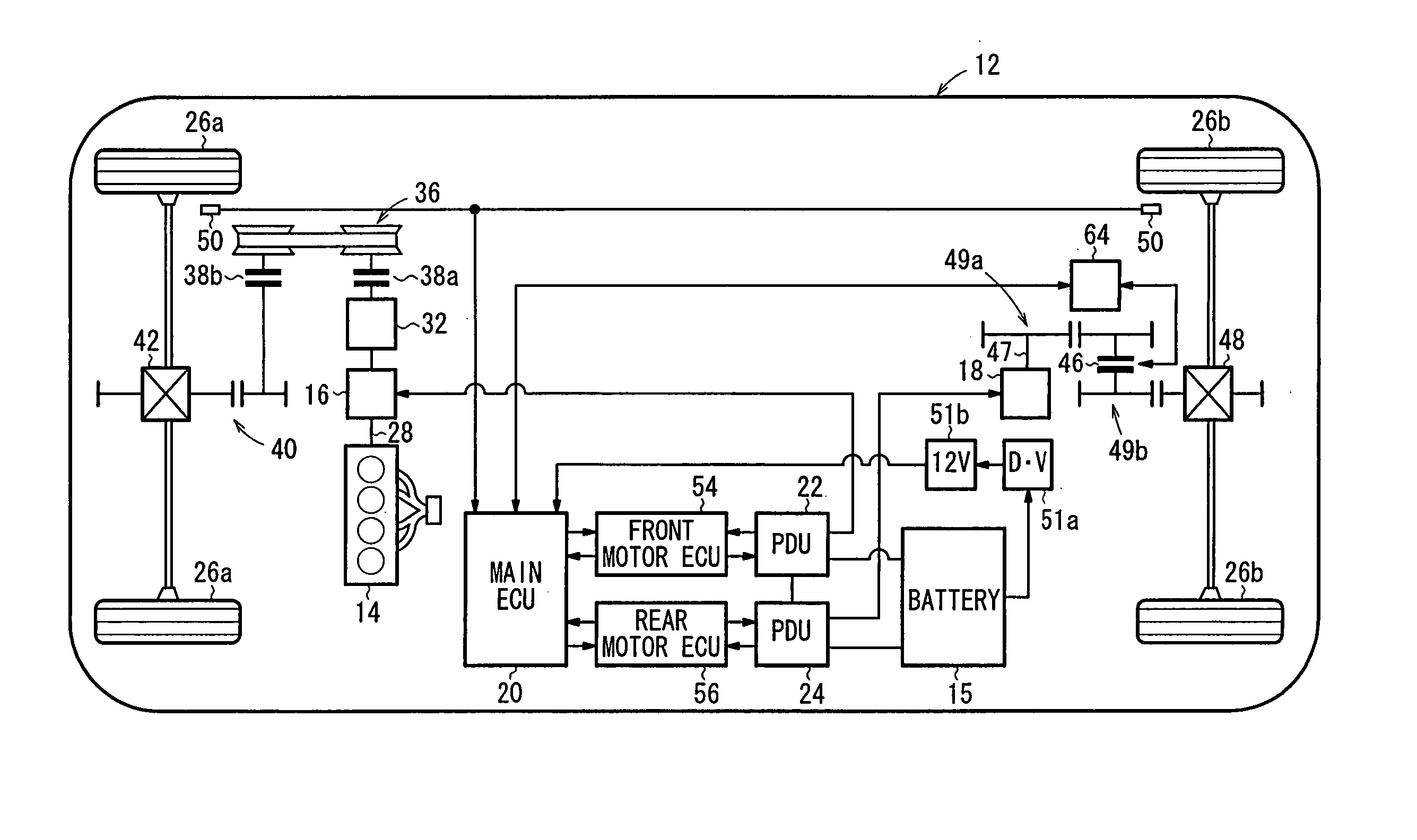
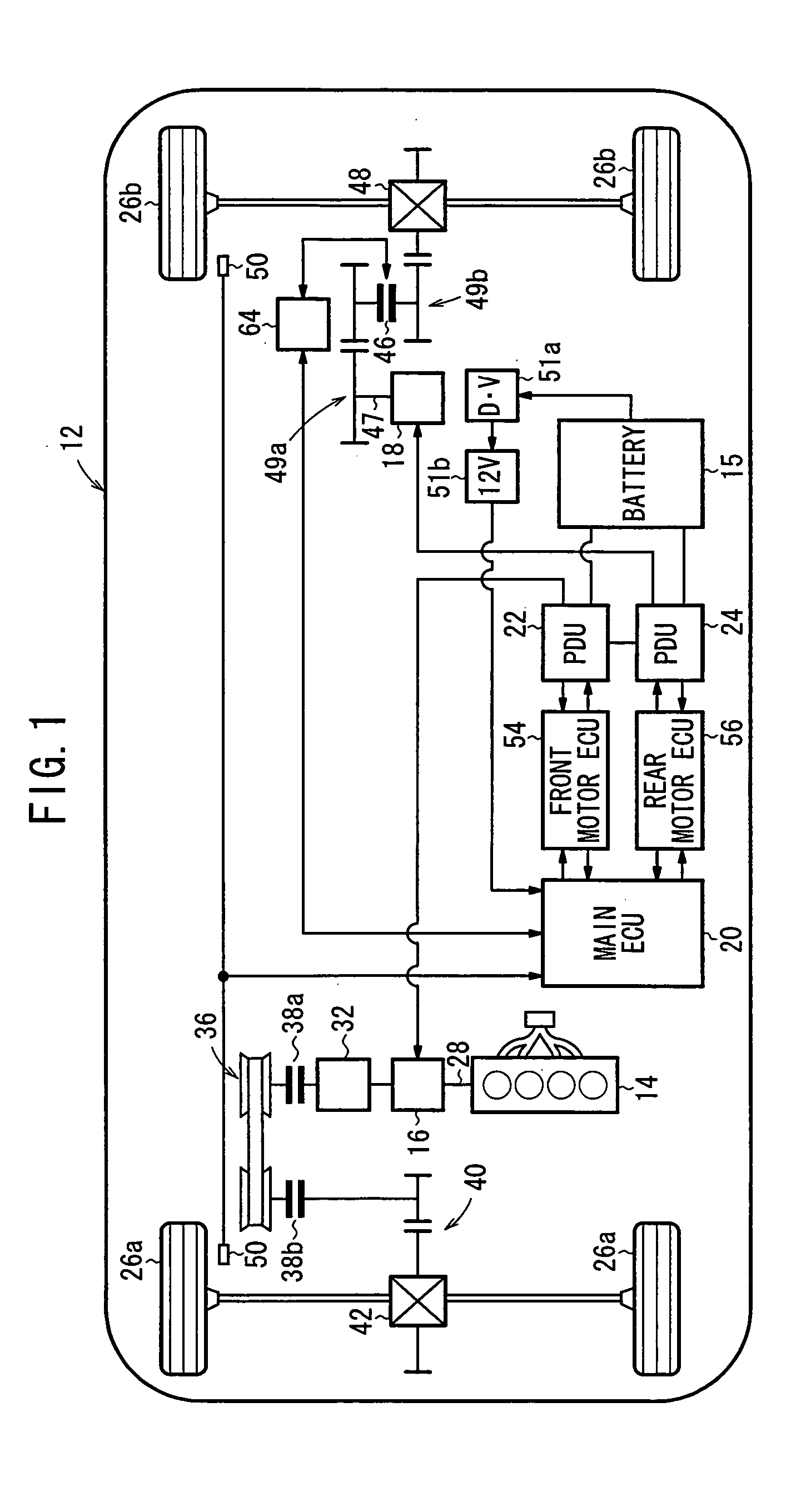
[0053]A drive control apparatus 10 (see FIG. 3) according to the embodiment of the present invention is incorporated in a hybrid vehicle 12 (see FIG. 1).

[0054]As shown in FIG. 1, the hybrid vehicle 12 is a four-wheel-drive vehicle and includes an internal combustion engine 14, a first motor 16 energized by electric power supplied from a high-voltage (e.g., 144 [V]) battery (first battery) 15, a second motor 18, and a main ECU (Electronic Control Unit) 20 for centralized management and control of the engine 14, the first motor 16, the second motor 18. The first motor 16 may comprise a slim motor that can be connected directly to the crankshaft of the engine 14.

[0055]The main ECU 20 comprises a microcomputer (not shown) made up of a RAM (Random Access Memory), a ROM (Read Only Memory), a CPU (Central Processing U...


PUM


Abstract

A rotational shaft receives drive power from an engine and a first motor, and drives front wheels through front clutches. A second motor drives rear wheels. The first motor and the second motor are supplied with electric power from a battery. A main ECU controls an electric vehicle mode in which the first clutches are disengaged, the supply of fuel to the engine is stopped, and the second motor drives the rear wheels to propel a hybrid vehicle, by dividing the electric vehicle mode into a first propulsion mode and a second propulsion mode. In the first propulsion mode, the first motor is de-energized. In the second propulsion mode, a load imposed on the second motor is greater than that of the first propulsion mode, and the first motor is supplied with electric power to rotate the rotational shaft at a predetermined speed.

Description

BACKGROUND OF THE INVENTION[0001]1. Field of the Invention[0002]The present invention relates to a drive control apparatus for a hybrid vehicle whose drive shaft is rotated by an engine and an electric motor, and more particularly to a drive control apparatus for a hybrid vehicle which has two motors for applying drive force (torque) to front and rear wheels of the hybrid vehicle.[0003]2. Description of the Related Art[0004]In recent years, hybrid vehicles having drive wheels rotated by an internal combustion engine and an electric motor have been widely developed. The hybrid vehicle operates in various modes including a so-called EV (Electric Vehicle) mode, in which the engine is disabled and the hybrid vehicle is run only by the motor, for reducing fuel consumption by the engine.[0005]When the hybrid vehicle needs a greater torque, or the electric power remaining in a battery on the hybrid vehicle is low, the engine is started. At this time, the battery is required to supply elect...

Claims


Application Information

Patent Timeline
Patent Type & Authority Patents(United States)
IPC IPC(8): B60K6/00B60W20/00B60K6/44B60K6/52B60K6/543B60K17/356B60L50/16B60W10/02B60W10/06B60W10/08F02D17/02F02D29/02F02D41/04F02N11/04F16H61/662
CPCB60K6/44B60K6/52B60W10/02B60W10/06B60W10/08B60W20/00B60K6/442Y02T10/76B60L2240/445B60L2240/486B60W2510/0604B60W2510/0671B60W2510/0676B60W2510/244B60W2520/10B60W2520/105B60W2530/16B60W2540/10B60W2540/12B60W2710/0616B60W2710/1061F16H61/662Y02T10/623Y02T10/6234Y02T10/6265Y02T10/6286Y02T10/62B60W20/40B60W2710/06B60W2710/08
Inventor YAMAMOTO, KAZUHISAKIRA, NOBUHIROKUBODERA, MASAOTATARA, YUSUKE
Owner HONDA MOTOR CO LTD
Why Eureka
Try Eureka