Method and system for high speed digital metering using overlapping envelopes

a digital metering and envelope technology, applied in the field of high-speed digital metering using overlapping envelopes, can solve the problems of system modules, envelopes, and modules not having time to perform their functions, and achieve the effect of high processing speed

Active Publication Date: 2006-05-09
DMT SOLUTIONS GLOBAL CORP
View PDF7 Cites 11 Cited by
  • Summary
  • Abstract
  • Description
  • Claims
  • Application Information

AI Technical Summary

Benefits of technology

[0014]The present invention provides a transporting system and method for use in a high velocity document processing system using lower velocity print technology. A transport path through the system is made up of an upstream transport conveying spaced apart documents at a first transport velocity. This first transport velocity represents the high processing speeds available in current high speed inserter machines. Downstream of the upstream transport, a deceleration transport decelerates documents from the high speed to a lower print velocity before passing the documents to a print transport. Both the upstream transport and the lower speed print transport normally operate at their respective constant velocities. The deceleration transport adjusts to match the speeds of the respective upstream or downstream modules when receiving and passing documents from them.

Problems solved by technology

At such a high rate of speed, system modules, such as those for sealing envelopes and putting postage on envelopes, have very little time in which to perform their functions.
If adequate control of spacing between envelopes is not maintained, the modules may not have time to perform their functions, and jams and other errors may occur.
In particular, postage meters are time sensitive components of a mail processing system.
Using mechanical print head technology, throughput speed for meters is limited by considerations such as the meter's ability to calculate postage and update postage meter registers, and the speed at which ink can be applied to the envelopes.
However, use of existing mechanical print technology with high speed mail processing machines presents some challenges.
First, some older mailing machines were not designed to operate at such high speeds for prolonged periods of time.
Another problem is that many existing mechanical print head machines are configured such that once an envelope is in the mailing machine, it is committed to be printed and translated to a downstream module, regardless of downstream conditions.
As a result, if there is a paper jam downstream, the existing mailing machine component could cause even more collateral damage to envelopes within the mailing machine.
At such high rates, jams and resultant damage may be more severe than at lower speeds.
Such damage often includes the result of moving envelopes crashing into the edges of stationary downstream envelopes.
Thus, while thermal inkjet technology is recognized as inexpensive, it is difficult to apply to high speed mail production systems that operate on mail pieces that are typically traveling in the range of up to 80 to 85 ips in such systems.
Although digital print technology exists that is capable of printing the requisite 300 dpi resolution on paper traveling at 80 to 85 ips, such devices are so expensive as to be considered cost prohibitive.
One problem with this current solution is that the conventional postage meters are inflexible in adjusting to conditions present in upstream or downstream meters.
This often results in an additional jam, and collateral damage, as the postage meter attempts to output the envelope to a stopped downstream module.
Another problem with the current solution is that it is very sensitive to gaps between consecutive envelopes.
In the process of slowing down the documents, the gap between documents is reduced, and an error in the spacing between documents becomes more significant.
The inserter may not be able to maintain controlled spacing between documents accurately enough to prevent collisions between consecutive envelopes during the slow down process.
This problem is further exacerbated because the R150 and R156 mailing machines are a bit too long to have time to carry out the routine on the envelopes, and to still have some margin for error in the arrival of a subsequent envelope.

Method used


Image

  • Method and system for high speed digital metering using overlapping envelopes
  • Method and system for high speed digital metering using overlapping envelopes
  • Method and system for high speed digital metering using overlapping envelopes

Examples


Embodiment Construction

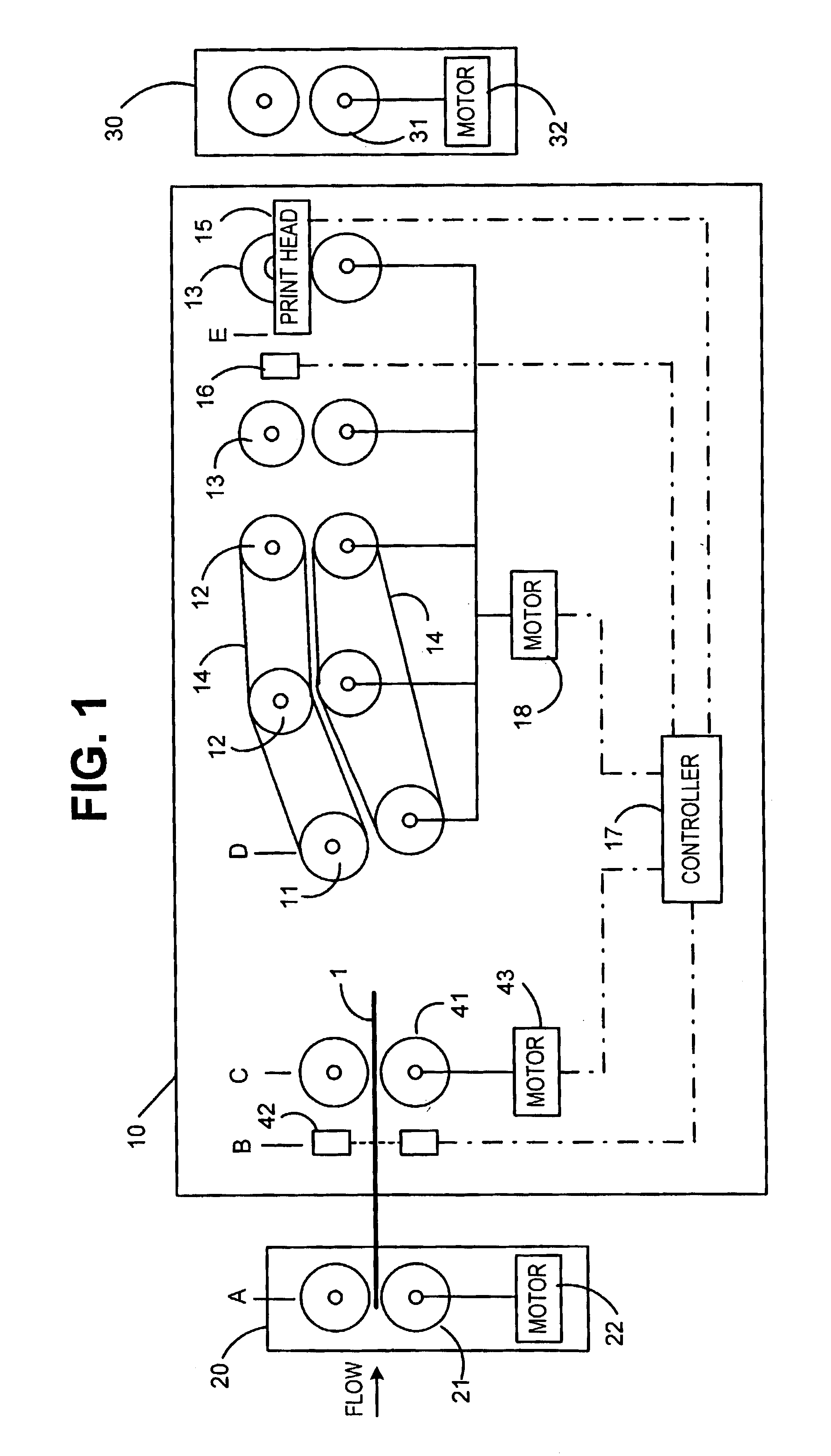
[0027]As seen in FIG. 1, the present invention includes a postage printing module 10 positioned between an upstream module 20 and a downstream module 30. Upstream and downstream modules 20 and 30 can be any kinds of modules in an inserter output subsystem. Typically the upstream module 20 could include a device for wetting and sealing an envelope flap. Downstream module 30 could be a module for sorting envelopes into appropriate output bins or a stacker module.

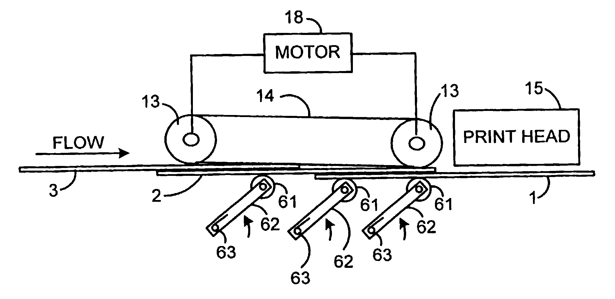
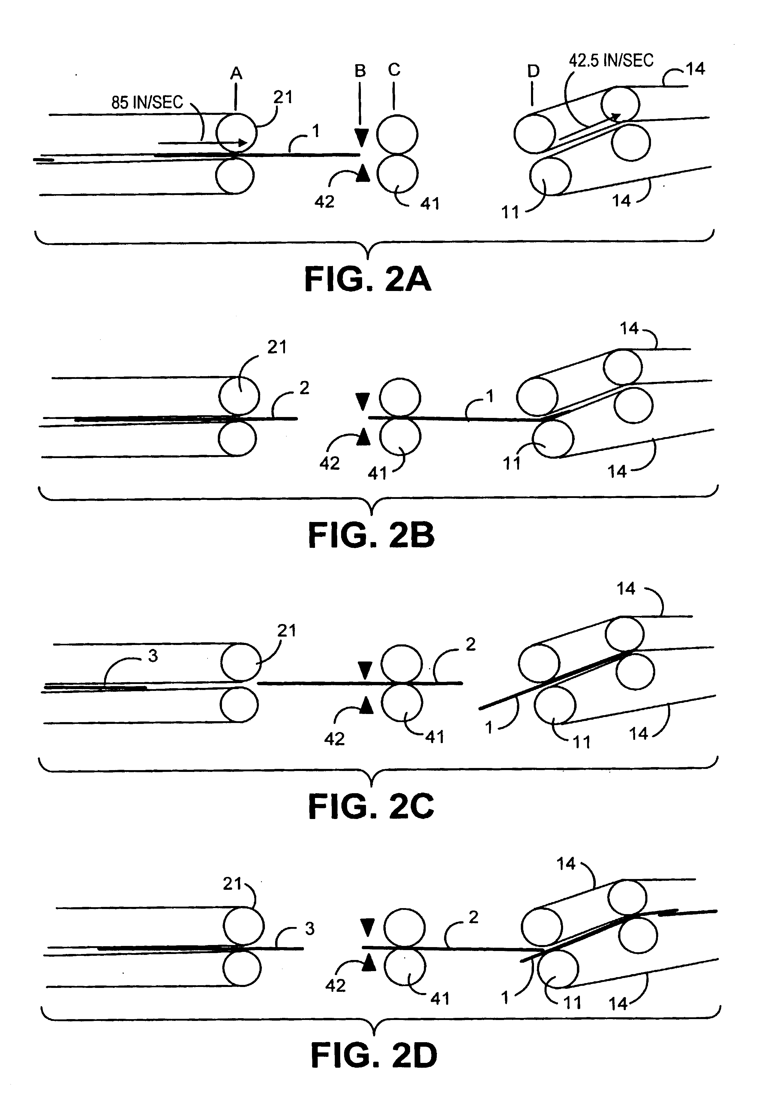
[0028]Postage printing module 10, upstream module 20, and downstream module 30, all include transport mechanisms for moving an envelope 1 along the processing flow path. In the depicted embodiment, the upstream module 20 includes nip rollers 21 driven by motor 22. Similarly, the downstream module 30 includes a transport comprised of nip rollers 31 driven by motor 32. In the preferred embodiment, rollers 21 and 31 are hard-nip rollers to minimize variation. As an alternative to nip rollers, the transport mechanism and transport...


PUM


Abstract

A transporting system and method for use in a high velocity document processing system using lower velocity print technology. The invention including an upstream transport conveying spaced apart documents at a first transport velocity. A deceleration transport decelerates documents from the high speed to a lower print velocity before passing the documents a print transport. A sensor located at the deceleration transport, detects the presence of documents at the deceleration transport, and triggers the deceleration profile to be performed on the document. The deceleration transport is controlled such that a leading portion of a document that is being decelerated overtakes a trailing portion of a downstream document that already traveling at the lower print velocity in the control of the print transport. An overlapping arrangement urges the lead portion of the upstream document to overlap on top of the trailing portion of the downstream document when the upstream document overtakes the downstream document. A print head prints on the transported documents at the print transport velocity.

Description

TECHNICAL FIELD[0001]The present invention relates to a module for printing postage value, or other information, on an envelope in a high speed mass mail processing and inserting system. Within the printing module, the printing device may operate at a lower velocity than other parts of the system. To allow the documents to be slowed for printing without causing jams, the present invention overlaps documents as they are transported and printed at the reduced speed.BACKGROUND OF THE INVENTION[0002]Inserter systems, such as those applicable for use with the present invention, are typically used by organizations such as banks, insurance companies and utility companies for producing a large volume of specific mailings where the contents of each mail item are directed to a particular addressee. Also, other organizations, such as direct mailers, use inserts for producing a large volume of generic mailings where the contents of each mail item are substantially identical for each addressee. ...

Claims


Application Information

Patent Timeline
Patent Type & Authority Patents(United States)
IPC IPC(8): B65H5/34B65H29/68B41J13/00B41J13/12B65H29/26B65H29/66
CPCB41J13/0018B41J13/12B65H29/68B65H29/6627B65H2701/1311
Inventor STEMMLE, DENIS J.
Owner DMT SOLUTIONS GLOBAL CORP
Why Eureka
Try Eureka