Modularized electronic device operating status display architecture

a technology of electronic devices and operating status, applied in the direction of cooling/ventilation/heating modifications, instruments, optical light guides, etc., can solve the problems of electronic system to shut down or fail to operate normally, large amount of heat, and high complexity of modularized fan assembly, so as to reduce the complexity of the structure and reduce the number of faults of the modularized fan unit. , the effect of convenient removal of faults

Inactive Publication Date: 2006-05-09
INVENTEC CORP
View PDF2 Cites 12 Cited by
  • Summary
  • Abstract
  • Description
  • Claims
  • Application Information

AI Technical Summary

Benefits of technology

[0007]It is therefore an objective of this invention to provide a modularized electronic device operating status display architecture which allows the assembly of the modularized fan unit with the chassis to be more simplified in structure to help increase productivity in the assembly of electronic systems.
[0010]Compared to prior art, since the invention can be implemented without having to mount the light-emitting diode on the outside of the chassis and use electrical wires to connect the light-emitting diode to the internally-located circuit card, it allows the assembly of the modularized fan unit to be less complex in structure and thus more increased in productivity. Furthermore, the invention allows maintenance personnel to conveniently remove a faulted modularized fan unit when seeing a fault-indicative light signal emitted from the modularized electronic device operating status display architecture of the invention, without having to first remove electrical wires on the modularized fan unit for removal of the modularized fan unit and then reconnect electrical wires after a new modularized fan unit is mounted in position, as in the case of prior art. This feature allows both assembly and maintenance of the modularized fan unit to be more convenient and efficient than prior art.

Problems solved by technology

Electronic systems typically produce large amounts of heat due to consumption of electrical power during operation, and if this heat is undissipated, it would result in burnout of electrical components or chips, thus causing the electronic system to shut down or fail to operate normally.
One drawback to conventional operating status display unit for modularized fan unit, however, is that the operating status detecting circuitry is typically located on the inside of the chassis, and therefore it requires the routing of electrical wires from the internal circuit card to the outside of the chassis so as to connect the operating status detecting circuitry to light-emitting diodes mounted on the outside of the chassis for the purpose of allowing assembly personnel or users to learn the current operating status of the modularized fan unit during operation by visually checking the light signal from the externally-mounted light-emitting diodes.
This practice would undoubtedly make the assembly of modularized fan unit to be more complex in structure and thus low in productivity.

Method used


Image

  • Modularized electronic device operating status display architecture
  • Modularized electronic device operating status display architecture
  • Modularized electronic device operating status display architecture

Examples


Embodiment Construction

[0016]A preferred embodiment of the modularized electronic device operating status display architecture according to the invention is disclosed in full details in the following with reference to the accompanying drawings.

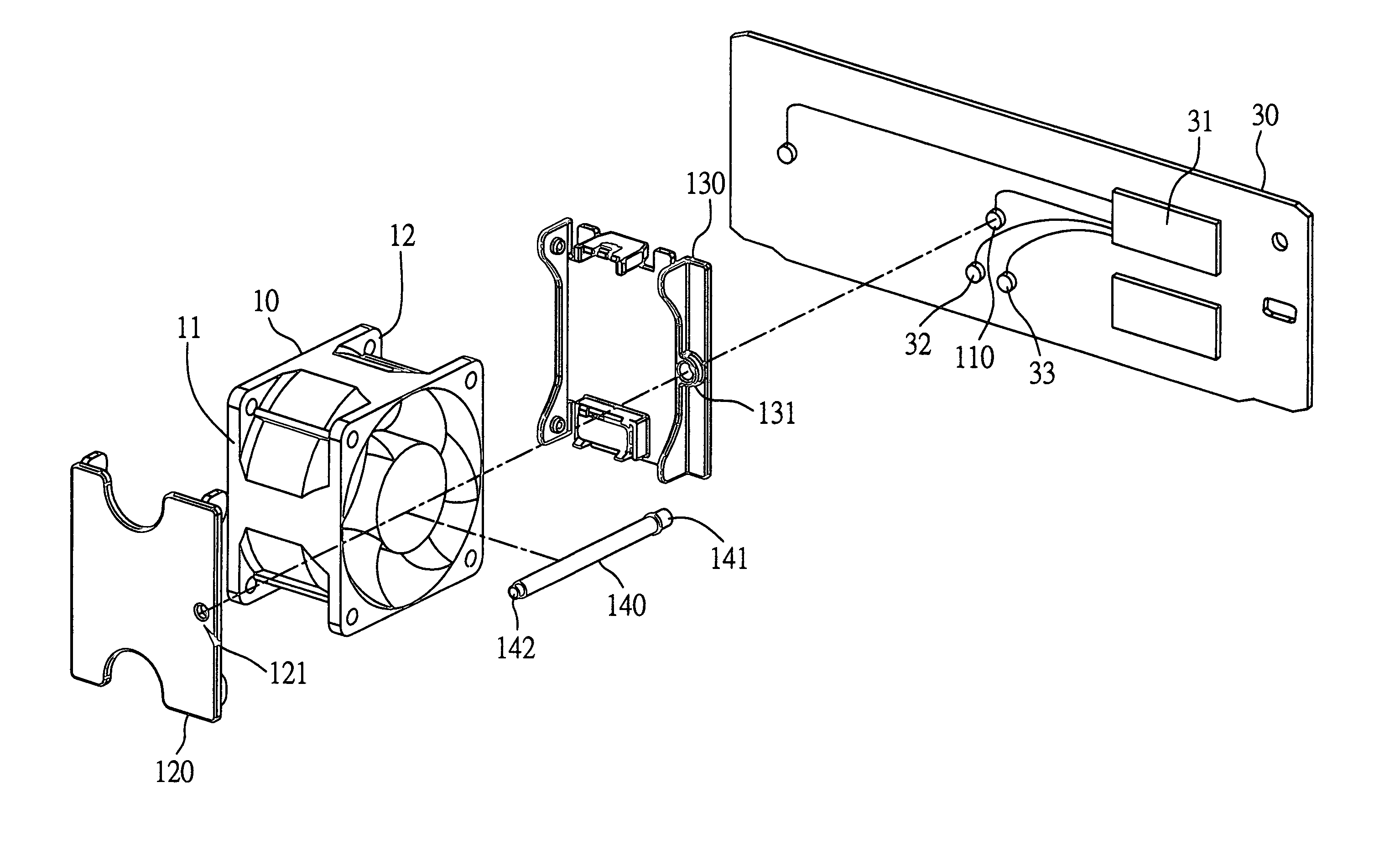
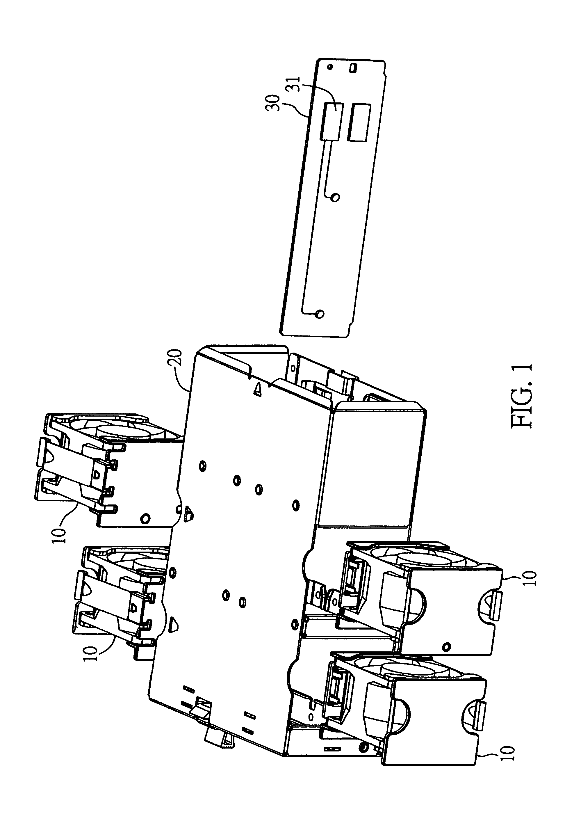
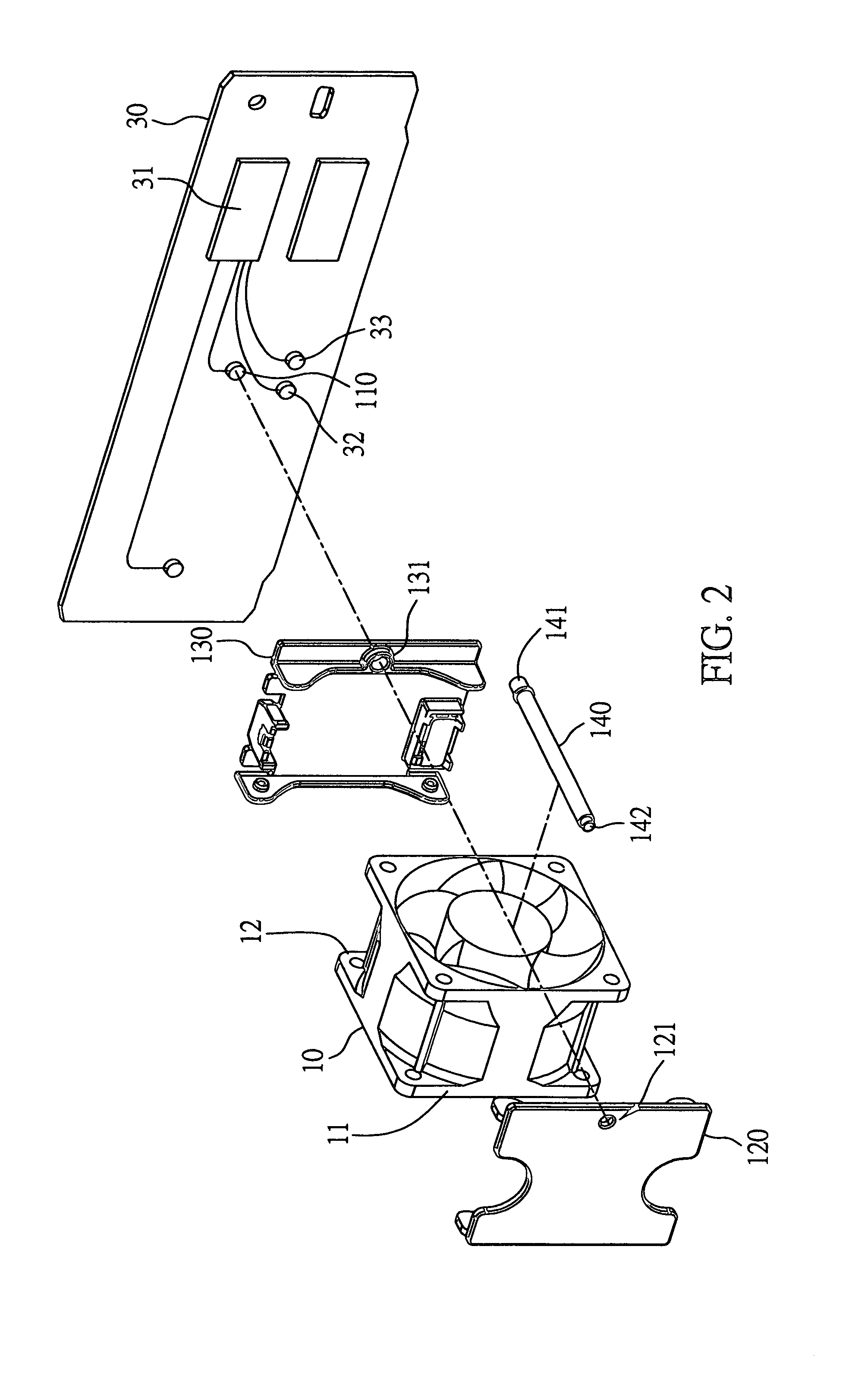
[0017]As shown in FIG. 1, the modularized electronic device operating status display architecture of the invention is designed for use in conjunction with one or more modularized electronic devices, such as modularized fan units 10, that are to be mounted to the inside of a chassis 20 of an electronic system, such as a network server or a desktop computer, and wherein the chassis 20 is further mounted with a circuit card 30 which is provided with an operating status detecting module 31, a plurality of signal contact points 32, and a plurality of power contact points 33 (shown in FIG. 2). When each modularized fan unit 10 in mounted in position on the inside of the chassis 20, the power contact points 33 will come in contact with corresponding power contact points (n...


PUM


Abstract

A modularized electronic device operating status display architecture is proposed, which is designed for use with a modularized electronic device mounted on the inside of a chassis of an electronic system, and which is capable of detecting whether the modularized electronic device operates normally during operation to thereby display its operating status as light signals on the outside of the chassis to allow assembly personnel or user to learn the operating status by visually checking the externally-displayed light signals. The proposed modularized electronic device operating status display architecture is more advantageous to use in that it allows the assembly to be less complex in structure and more increased in productivity. Furthermore, it allows no removal and reconnection of electrical wires during the replacement of a faulted modularized device. This feature allows both assembly and maintenance of the modularized fan unit to be more convenient and efficient than prior art.

Description

BACKGROUND OF THE INVENTION[0001]1. Field of the Invention[0002]This invention relates to electronic system assembly technology, and more particularly, to a modularized electronic device operating status display architecture which is designed for use with a modularized electronic device, such as a modularized fan unit, that is to be mounted on the inside of a chassis of an electronic system, such as a Web server or a desktop computer, and which is capable of detecting whether the modularized electronic device operates normally when the modularized electronic device is mounted in position in the chassis and displaying the operating status of the modularized electronic device as light signals on the outside of the chassis so as to allow assembly personnel or user to learn the operating status of the modularized electronic device by visually checking the externally-displayed light signals.[0003]2. Description of Related Art[0004]Electronic systems typically produce large amounts of hea...

Claims


Application Information

Patent Timeline
Patent Type & Authority Patents(United States)
IPC IPC(8): G02B6/00G02B6/36H05K7/20
CPCH05K7/20172
Inventor HSU, CHENG-CHUNG
Owner INVENTEC CORP
Why Eureka
Try Eureka