
Stable area detection device of platen gap and recording apparatus

a detection device and platen gap technology, applied in the field of recording equipment, can solve problems such as failure to get accurate platen gap, and achieve the effects of reducing the possibility of damaging the recording head, reducing the possibility of damage, and detecting easily

Active Publication Date: 2006-05-09
SEIKO EPSON CORP
View PDF10 Cites 6 Cited by
  • Summary
  • Abstract
  • Description
  • Claims
  • Application Information

AI Technical Summary

Benefits of technology

[0022]According to the first aspect of the invention, since the gap adjuster cam is prevented from standing in the transition area where there is a change in the platen gap, it is possible to perform the recording on the recording medium at high quality.
[0028]the rotational member is provided with anther detection object for the home position detection sensor at a position where the gap adjuster cam is located in a home position. According to this aspect, since the home position of the gap adjuster cam can be detected easily, it can contribute to the improvement of throughput.
[0029]The stable area detection device of platen gap according to the fifth aspect of the invention is constituted in that, in addition to the fourth aspect, the position where the gap adjuster cam is located in the home position is a boundary portion between the stable area of a maximum platen gap stage and the transition area adjacent to the stable area of the maximum platen gap stage. According to this aspect, even when a user turns on the printer without knowing there is foreign substance under the recording head, since the platen gap is enough, it is possible to decrease a possibility of damaging the recording head owing to the foreign substance, through the scanning operation of the recording head.

Problems solved by technology

When the turning phase angle of the cam a little deviates because of tolerance, the platen gap is determined at the transition area and accordingly there is a possibility of failing to get the accurate platen gap.

Method used


Image

  • Stable area detection device of platen gap and recording apparatus
  • Stable area detection device of platen gap and recording apparatus
  • Stable area detection device of platen gap and recording apparatus

Examples


Embodiment Construction

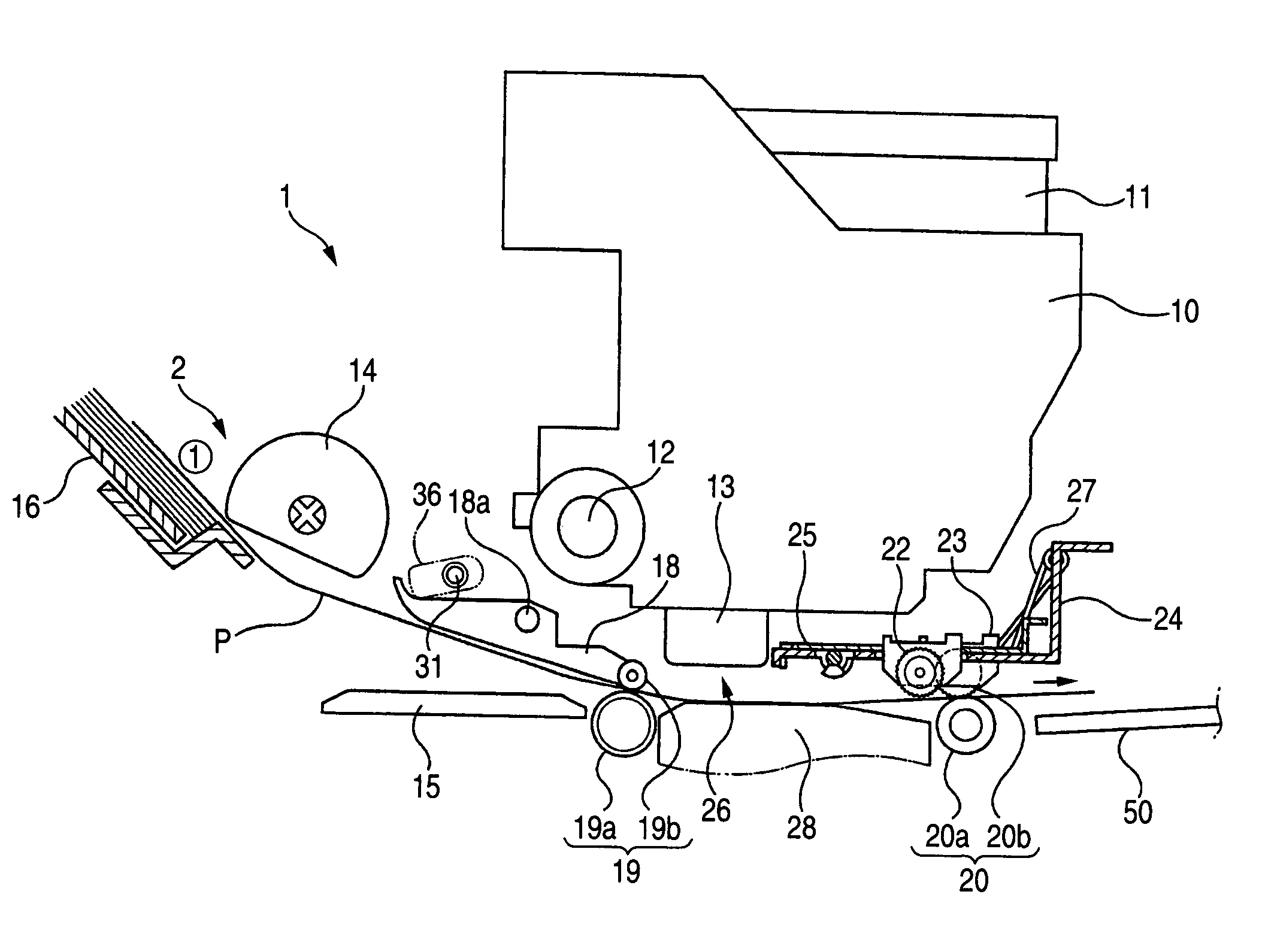
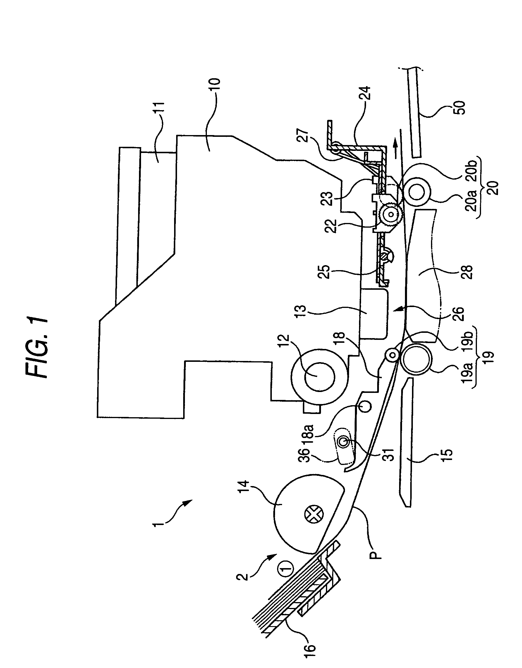
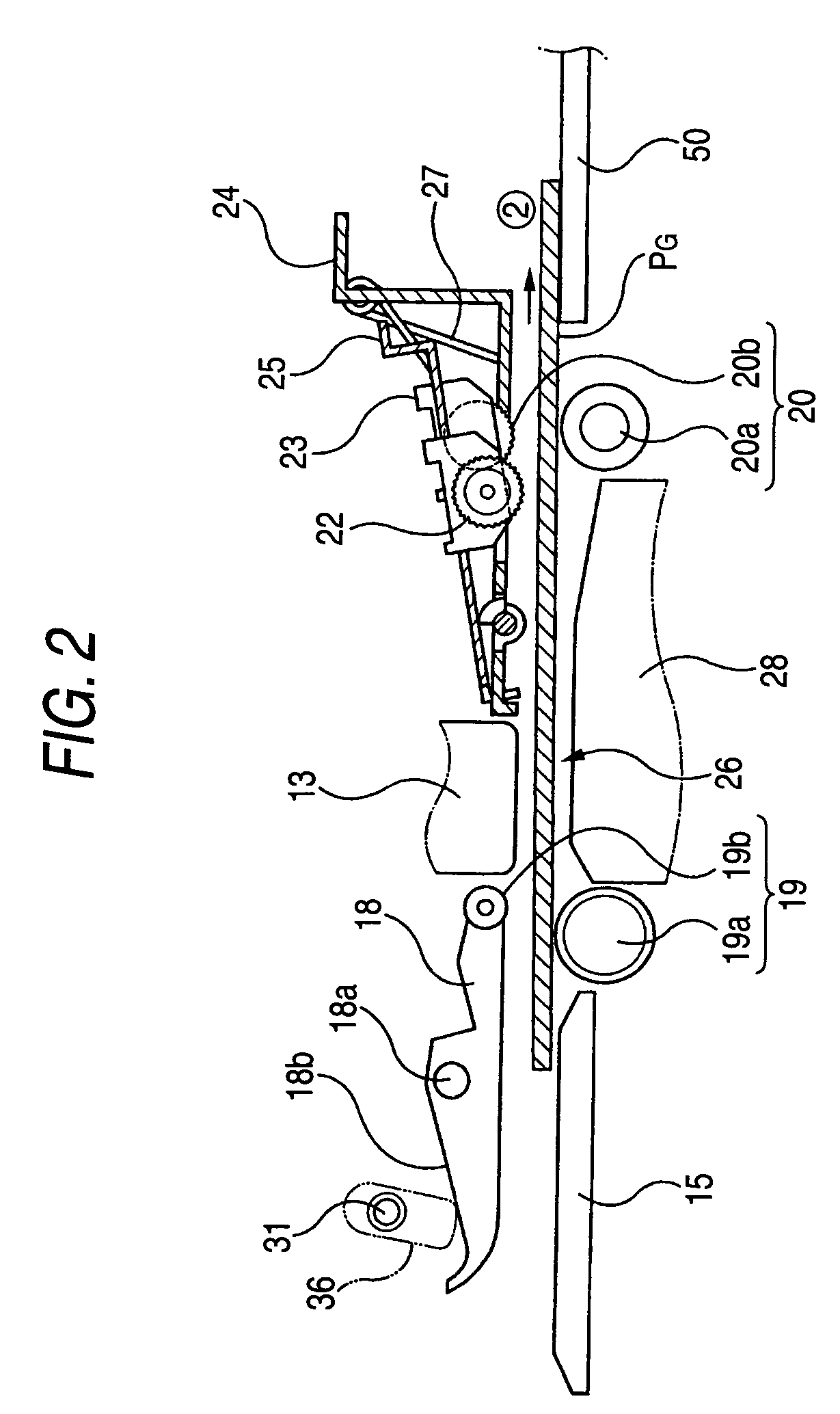
[0051]Hereinafter, a first embodiment of the present invention will be described with reference to the drawings. FIG. 1 is a cross sectional side view showing an ink jet printer (hereinafter, referred to as a printer) as one example of a recording apparatus including a stable area detection device of platen gap, according to the invention, FIG. 2 is a cross sectional side view showing the state of feeding a stiff recording medium, FIG. 3 is a perspective view of a transport-driven roller holder and its vicinity when feeding a flexible recording medium. Although the invention can be applied to an ejection medium on which surface, instead of ink, liquids corresponding to other applications are ejected, other than the recording medium such as paper and the like, the recording medium will be hereafter described representatively.

[0052]A printer 1 comprises a feeding section 2 for feeding a recording medium P, at the upstream side and the feeding section 2 keeps a stack of the recording m...


PUM


Abstract

In a platen gap adjustment device, a stable area detection device for a platen gap formed between ahead and an upper surface of a platen, wherein the carriage guide shaft is moved relatively to the platen so that the platen gap is adjusted by driving the drive motor to rotate the gap adjuster cam, the gap adjuster cam is configured so as to provide a plurality of stable areas and a plurality transition areas; and wherein a stable area detection sensor is provided so as to face to a rotational member which rotates synchronously with the gap adjuster cam, and a detection object in correspondence with the stable areas of the platen gap is provided on the rotational member.

Description

[0001]The present application is based on Japanese Patent Applications Nos. 2003-100638 and 2003-343646, the entire contents of which are incorporated herein by reference.BACKGROUND OF THE INVENTION[0002]1. Field of the Invention[0003]The present invention relates to a recording apparatus. Further, the invention relates to a liquid ejecting device such as an ink jet recording apparatus for ejecting liquid such as ink from its head into an ejection medium.[0004]The liquid ejecting device is not restricted to a recording apparatus including a printer, a copy, and a facsimile which uses an inkjet recording head in order to discharge the ink therefrom into the recording medium, for performing a recording, but it includes a liquid ejection apparatus for ejecting the liquid corresponding to the same purpose, instead of ink, into the ejection medium corresponding to the recording medium, from a liquid ejection head corresponding to the recording head and attaching the above liquid to the e...

Claims


Application Information

Patent Timeline
IPC IPC(8): B41J11/20B41J25/308
CPCB41J25/308
Inventor TAKESHITA, SANSHIROYAMAGUCHI, KAZUHIKOSUGIMOTO, HIROYUKI
Owner SEIKO EPSON CORP
Learn More