Elliptical exercise methods and apparatus

a technology of elliptical exercise and apparatus, applied in the field of relativly compact exercise equipment, can solve the problems of unsatisfactory fixed aspect ratio, undesirable compromises made to arrive at the prior art machine,

Inactive Publication Date: 2006-05-09
STEARNS KENNETH W +1
View PDF9 Cites 44 Cited by
  • Summary
  • Abstract
  • Description
  • Claims
  • Application Information

AI Technical Summary

Benefits of technology

[0013]The present invention may be described in terms of linkage assemblies and corresponding exercise apparatus which link circular motion to relatively more complex, generally elliptical motion. More specifically, left and right cranks are rotatably mounted on a frame to provide rotating left and right connection points which define a crank diameter therebetween. Left and right foot supporting linkages are movably interconnected between the frame and respective connection points in such a manner that rotation of the cranks is linked to generally elliptical movement of left and right foot platforms. The linkages include foot supporting members which are connected, but not coupled, to respective connection points for purposes of determining vertical movement of a person's feet (as a function of the crank diameter). The linkages also include drawbar arrangements which determine horizontal movement of the person's feet (independent of the crank diameter). These “decoupled” foot platforms or dual drive assemblies facilitate increases in stride length and / or decreases in machine length.
[0014]On a preferred embodiment, the foot supporting members are positioned adjacent one another and between opposite side cranks, thereby accommodating movement of a person's feet between the cranks. This sort of arrangement allows for shorter machines without sacrificing stride length. At least one guard or shield may be provided between the foot platforms to eliminate pinch points and / or reduce the likelihood of the user's feet or ankles striking one another during exercise.

Problems solved by technology

It is somewhat problematic to describe or compare the respective locations of and / or paths traveled by a person's feet on the Miller machines and the Eschenbach machines because the analysis depends upon the size of a person's feet.
Unfortunately, this fixed aspect ratio is contrary to real life activity, since a person does not typically lift his legs higher and higher while taking strides which are longer and longer.
As a result of the direct relationship between horizontal foot travel and vertical foot travel, undesirable compromises were made to arrive at the prior art machines discussed above.

Method used


Image

  • Elliptical exercise methods and apparatus
  • Elliptical exercise methods and apparatus
  • Elliptical exercise methods and apparatus

Examples


Embodiment Construction

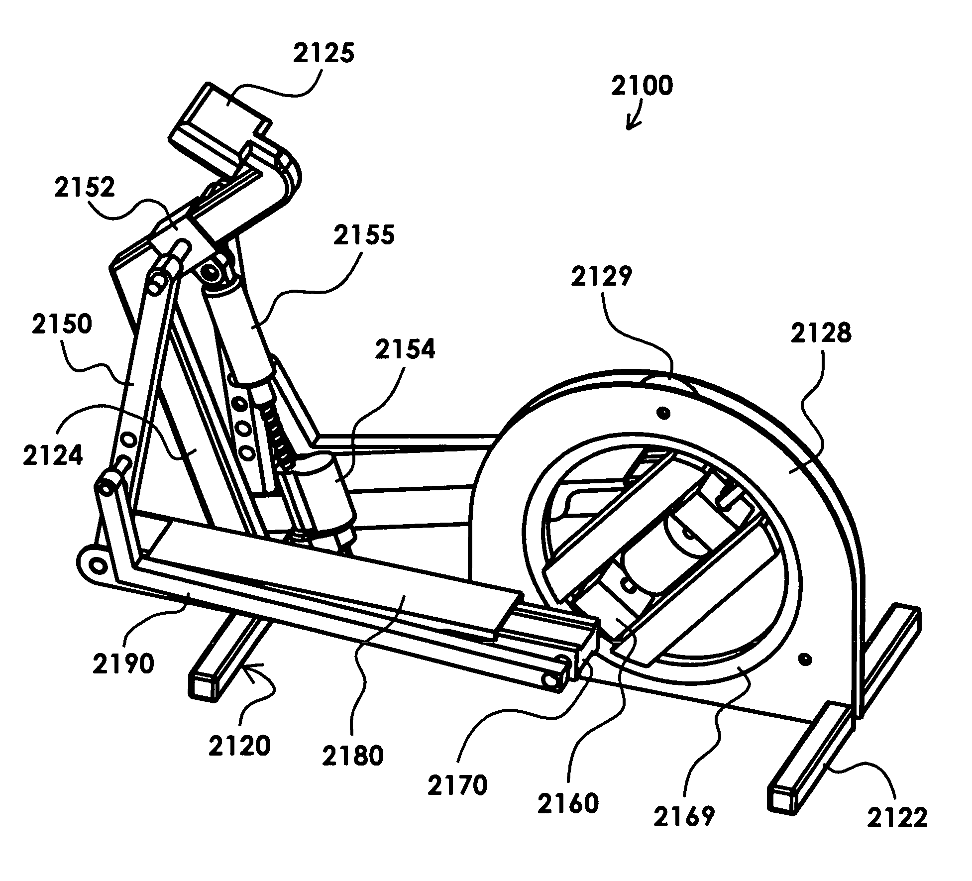
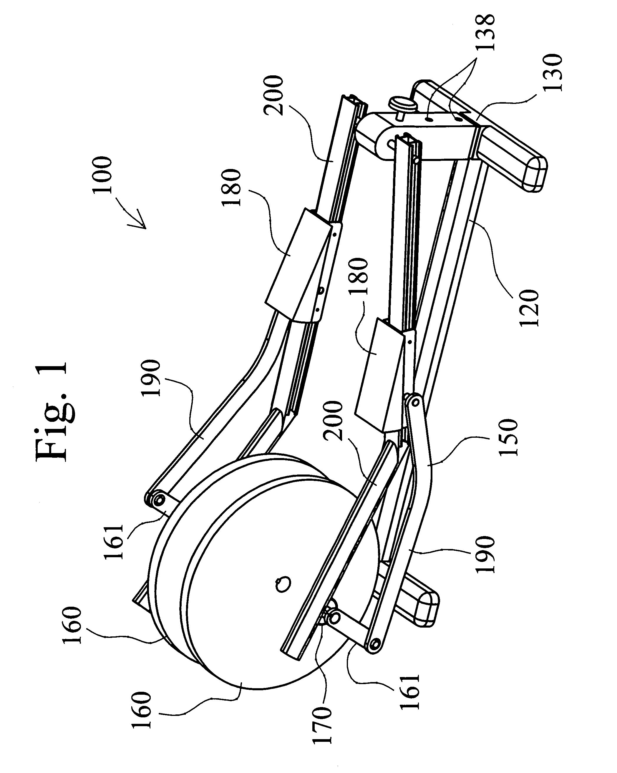
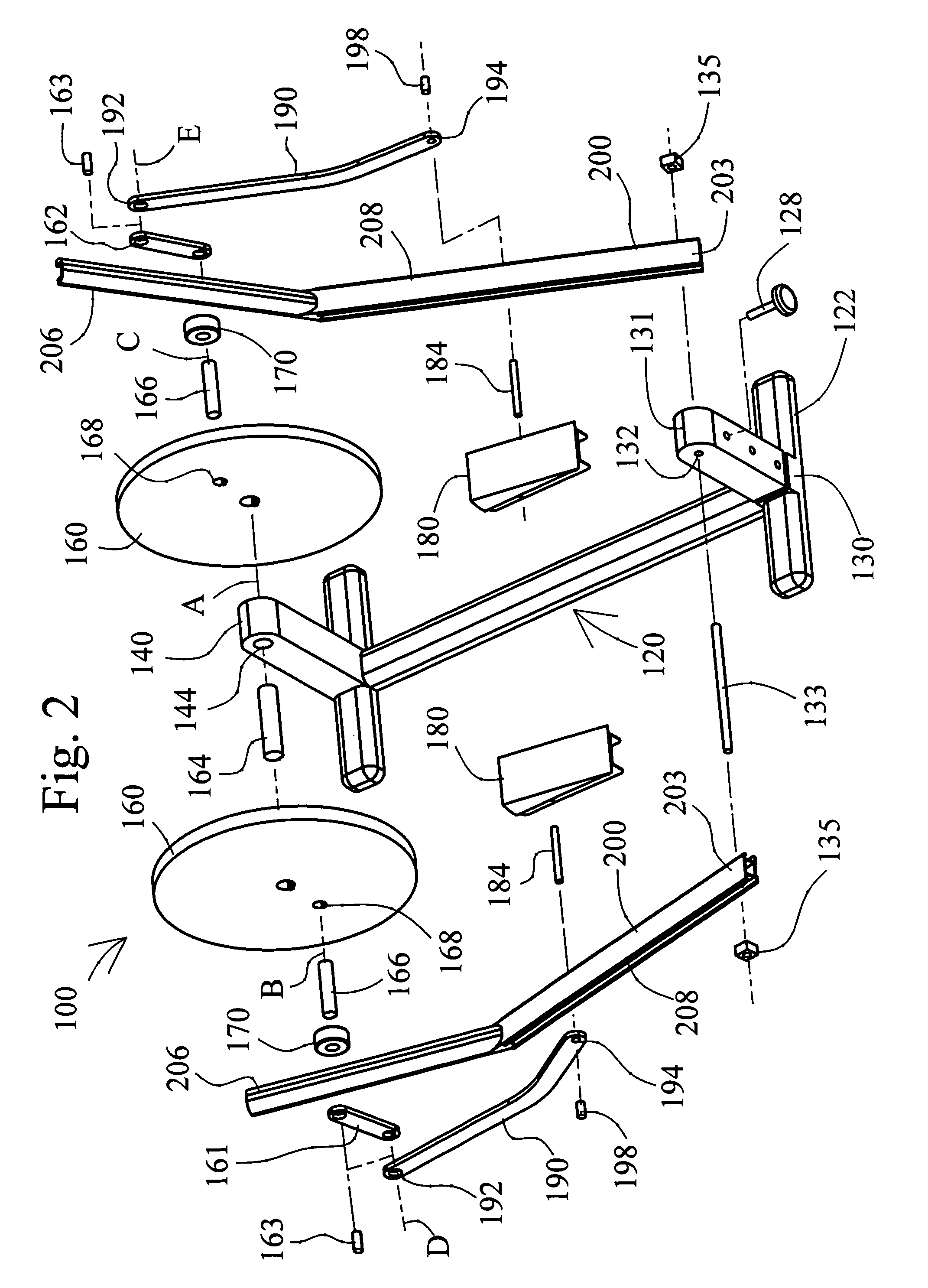
[0068]The present invention provides various elliptical motion exercise machines which link rotation of left and right cranks to generally elliptical motion of respective left and right foot supports. The term “elliptical motion” is intended in a broad sense to describe a closed path of motion having a relatively longer, major axis and a relatively shorter, minor axis (which extends perpendicular to the first axis). All of the above-identified “elliptical” patents are incorporated herein by reference.

[0069]In general, the machines may be said to use displacement of the cranks to move the foot supports in a direction coincidental with the minor axis, and displacement of crank driven members to move the foot supports in a direction coincidental with the major axis. A general characteristic of the present invention is that the crank diameter which determines the length of the minor axis does not also determine the length of the major axis. As a result of this characteristic, a person's...


PUM


Abstract

Various exercise apparatus have respective linkage assemblies which are movably mounted on a frame and link rotation of left and right cranks to elliptical movement of left and right foot supporting members. The linkage assemblies include separate linkage arrangements for horizontal and vertical displacement of the foot supporting members, and the linkage assemblies accommodate travel of the foot supporting members to positions laterally adjacent the cranks.

Description

CROSS-REFERENCE TO RELATED APPLICATIONS[0001]This application is a continuation of U.S. patent application Ser. No. 09 / 638,099, filed on Aug. 11, 2000 (now U.S. Pat. No. 6,629,909), which in turn (1) is a continuation-in-part of U.S. patent application Ser. No. 09 / 072,765, filed on May 5, 1998 (now U.S. Pat. No. 6,171,215), which in turn, is a continuation-in-part of both U.S. patent application Ser. No. 08 / 839,990, filed on Apr. 24, 1997 (now U.S. Pat. No. 5,893,820), and U.S. patent application Ser. No. 09 / 064,393, filed on Apr. 22, 1998 (now U.S. Pat. No. 5,882,281), the latter of which, in turn, is a continuation-in-part of U.S. patent application Ser. No. 08 / 839,991, filed on Apr. 24, 1997 (now U.S. Pat. No. 5,803,871); and (2) is a continuation-in-part of U.S. patent application Ser. No. 09 / 678,352, filed on Oct. 3, 2000 (now U.S. Pat. No. 6,849,033), which is a continuation of U.S. patent application Ser. No. 09 / 066,143, filed on Apr. 24, 1998 (now U.S. Pat. No. 6,126,574), w...

Claims


Application Information

Patent Timeline
Patent Type & Authority Patents(United States)
IPC IPC(8): A63B22/04A63B22/12
CPCA63B22/001A63B22/0012A63B22/0023A63B22/0664A63B21/0058A63B21/225A63B2230/75A63B2022/002A63B2022/067A63B2071/009A63B2220/30A63B2225/20
Inventor STEARNS, KENNETH W.MARESH, JOSEPH D.
Owner STEARNS KENNETH W
Why Eureka
Try Eureka