Gas discharge lamp base comprising an ignition device

a technology of gas discharge and lamp base, which is applied in the direction of protective devices for lighting, cathode-ray/electron-beam tube circuit elements, inductance with magnetic core, etc., can solve the problems of considerable manual work and complicated construction of known lamp base, and achieve the effect of saving individual parts

Inactive Publication Date: 2006-05-09
VOGT ELECTRONICS AKTIENGES
View PDF9 Cites 34 Cited by
  • Summary
  • Abstract
  • Description
  • Claims
  • Application Information

AI Technical Summary

Benefits of technology

[0018]Components in MID technology (Molded Interconnect Devices) are molded parts with an integrated conductor structure (3D). Apart from the integration of electronics and mechanics, they make it possible to save individual parts. M...

Problems solved by technology

However, the known lamp base is quite complicated in the way in which it is constructed and produced, ...

Method used


Image

  • Gas discharge lamp base comprising an ignition device
  • Gas discharge lamp base comprising an ignition device
  • Gas discharge lamp base comprising an ignition device

Examples


Embodiment Construction

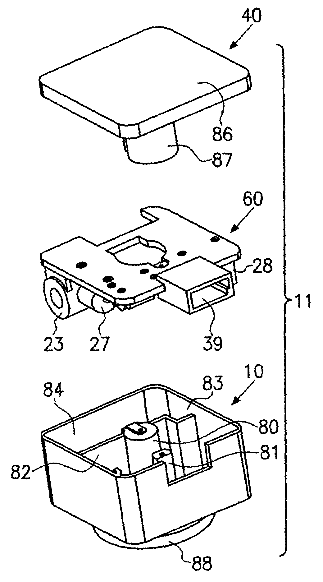
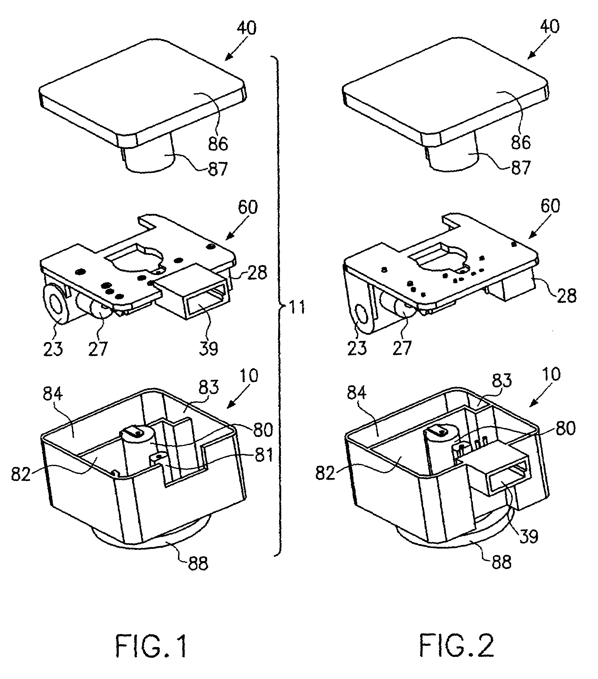
[0031]FIG. 1 shows the three main component parts of the gas-discharge lamp base 11 according to the invention, with the upper housing part 10, the leadframe 60 and the lower housing part or cover 40. The upper housing parts 10 have a central stub 80 and a lateral stub 81 of a smaller diameter, through which the leads to the lamp (not shown here), to be placed on from below, are led. When this happens, the conductor in the central stub 80 is placed onto the upper face of the latter from the outside and subsequently cast. A dividing wall 82 in the upper housing part 10 forms a chamber 84, having a stepped indent or recess 83. In the case of the embodiment of FIG. 2, the collar 39 for receiving the plug is formed onto the housing of the upper part 10′. The leads are identifiable as upright red marks, in the same way as the foot contact on the stub 80.

[0032]In the case of the embodiment according to FIG. 1, the collar 39 is formed onto the leadframe 60. The leadframe 60 carries the bar...


PUM


Abstract

A description is given of a gas-discharge lamp base (11) with a housing comprising an upper part (10) and a cover (40), a support (16) accommodated in the housing for receiving the components, with a transformer, with inductances connected in series with the lamp (1) and a capacitance connected in parallel with the lamp (1), the transformer comprising a bar transformer (23). This construction permits particularly efficient production, because the support can be constructed as a simple leadframe which permits automatic component fitting.

Description

CROSS-REFERENCE TO RELATED APPLICATION[0001]This application is a National Phase of International Application Serial No. PCT / EP01 / 15036, filed Dec. 19, 2001.BACKGROUND OF THE INVENTION[0002]1. Field of the Invention[0003]The invention relates to a gas-discharge lamp base with igniting device of the type known from WO 00 / 59269 (D1).[0004]2. Description of the Background Art[0005]In the case of the known gas-discharge lamp base, the voltage supply and the igniting device for the lamp, and consequently a voltage of about 30 kV, have been successfully “accommodated” in a space of about 4×4×3 cm. However, the known lamp base is quite complicated in the way in which it is constructed and produced, since most of its components cannot be fitted automatically. Therefore, considerable manual work is necessary.SUMMARY OF THE INVENTION[0006]The invention is based on the object of providing a gas-discharge lamp base which is of a simpler construction and permits automatic component fitting.[0007...

Claims


Application Information

Patent Timeline
IPC IPC(8): H05B37/00F21V15/04F21V19/00H05B37/02H05B37/03H05B41/00H05B41/04
CPCF21S48/1109H05B41/042F21S48/1186F21S41/192
Inventor NEUMEIER, KLAUSDUSCHL, ANTONGAISBAUER, ERWINWINKLER, JOHANNSCHICHL, ROMAN
Owner VOGT ELECTRONICS AKTIENGES
Why Eureka
Try Eureka