Apparatus and methods for induction-SFL logging

a technology of induction-sfl logging and logging apparatus, which is applied in the direction of instruments, measurement devices, scientific instruments, etc., can solve the problems of resistance measurement having unwanted contributions, shoulder effects, and particularly problematic effects

Inactive Publication Date: 2006-05-09
SCHLUMBERGER TECH CORP
View PDF35 Cites 20 Cited by
  • Summary
  • Abstract
  • Description
  • Claims
  • Application Information

AI Technical Summary

Benefits of technology

[0067]The advantages of the present invention include efficient apparatus and methods through reduced tool length. A tool in accordance with the invention allows wells to be drilled with less rathole, which in turn reduces drilling time. A shorter tool has a lower risk of sticking. In addition, a shorter tool string may improve the chance of reaching the bottom of the well, particularly when there are doglegs or curvatures in the well. The result is quicker operations and in turn significant rig time savings. A tool in accordance with the invention also requires less frequent sampling interval, which allows for a logging speed that may be as much as twice that of a comparable tool, e.g. an AIT™.

Problems solved by technology

For example, the resistivity measurements may have unwanted contributions from currents flowing in the sedimentation layers (beds) lying above and below the layer under investigation.
This is referred to as shoulder effects, which are particularly problematic if the layer under investigation is less conductive than the adjacent beds.
In addition to the shoulder effects discussed above, skin effects may also limit the ability of the induction logging equipment to accurately measure the true conductivity of the formations.
However, large transmitter-receiver spacing increases the percentage of non-linearity of the responses resulting from the skin effects.
A large transmitter-receiver spacing also increases tool length and cost.
However, to achieve a high resolution, the transmitter-receiver spacing needs to be small; this reduces the DOI of the tool.
However, high frequency is more susceptible to skin effects (hence, shallower DOI).
Mutual inductance between the transmitter and the receiver coils can severely impact the measurable signal magnitudes.
As a result, the logging tools tend to be long.
In addition, a long tool has a tendency of getting stuck in wellbores having poor borehole conditions and cannot be placed into wellbores having severe dog legs or horizontal wells having a short kickoff radius.

Method used


Image

  • Apparatus and methods for induction-SFL logging
  • Apparatus and methods for induction-SFL logging
  • Apparatus and methods for induction-SFL logging

Examples


Embodiment Construction

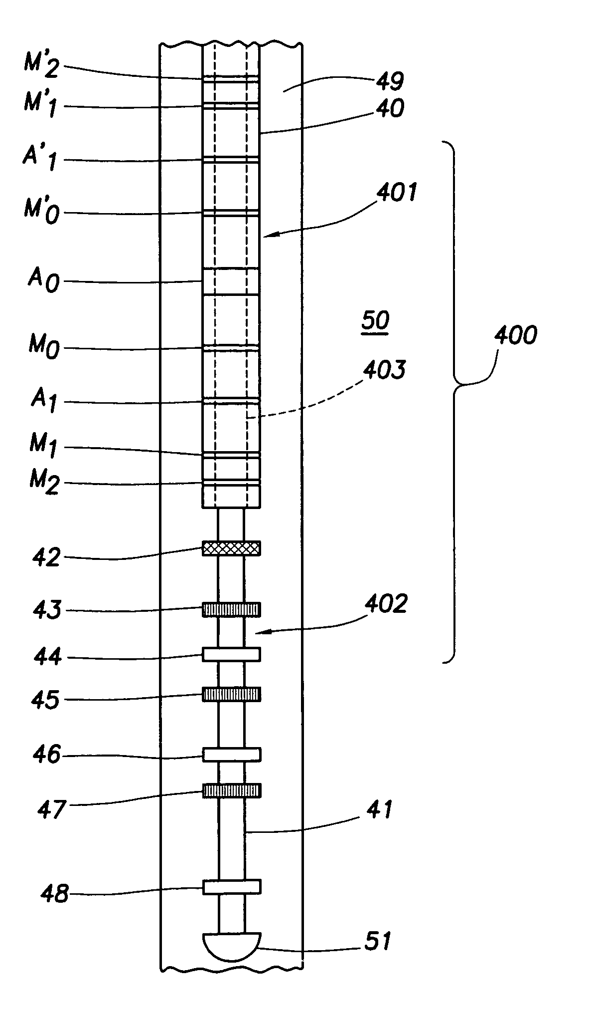
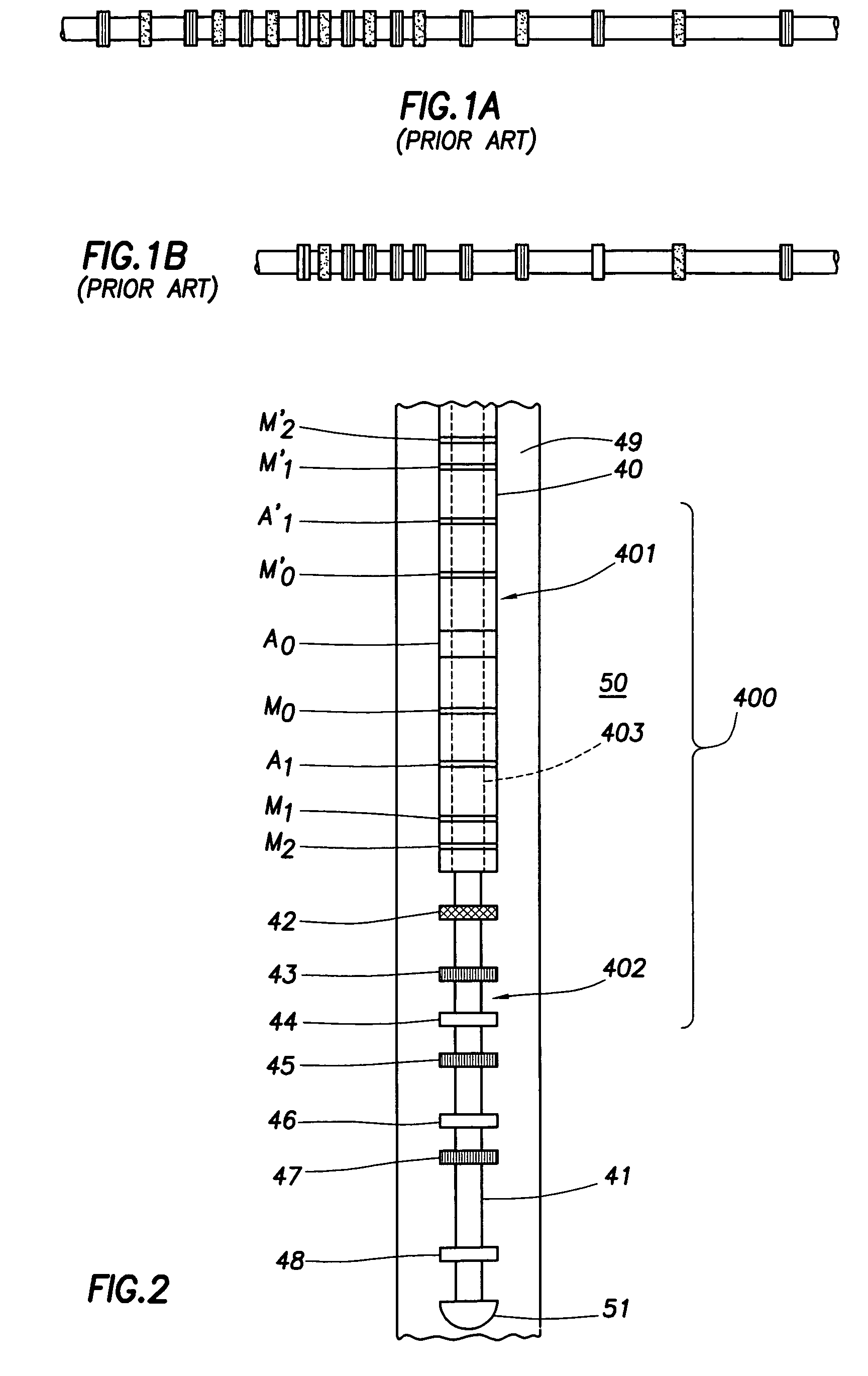
[0033]The present invention relates to apparatus and methods for measuring formation resistivity. A logging tool in accordance with embodiments of the invention has simplified components and yet can provide measurements that are comparable to more sophisticated tools. In addition, a tool in accordance with embodiments of the invention is capable of providing depths of investigation comparable to the prior art tools such that measurements made with tools of the invention may be compared with those from other tools. Thus, embodiments of the invention use a simple approach to satisfy the industry demand for efficient and cost effective apparatus and methods, and at the same time address the desire for accuracy of measurement and the possibility of correlating with old well logs.

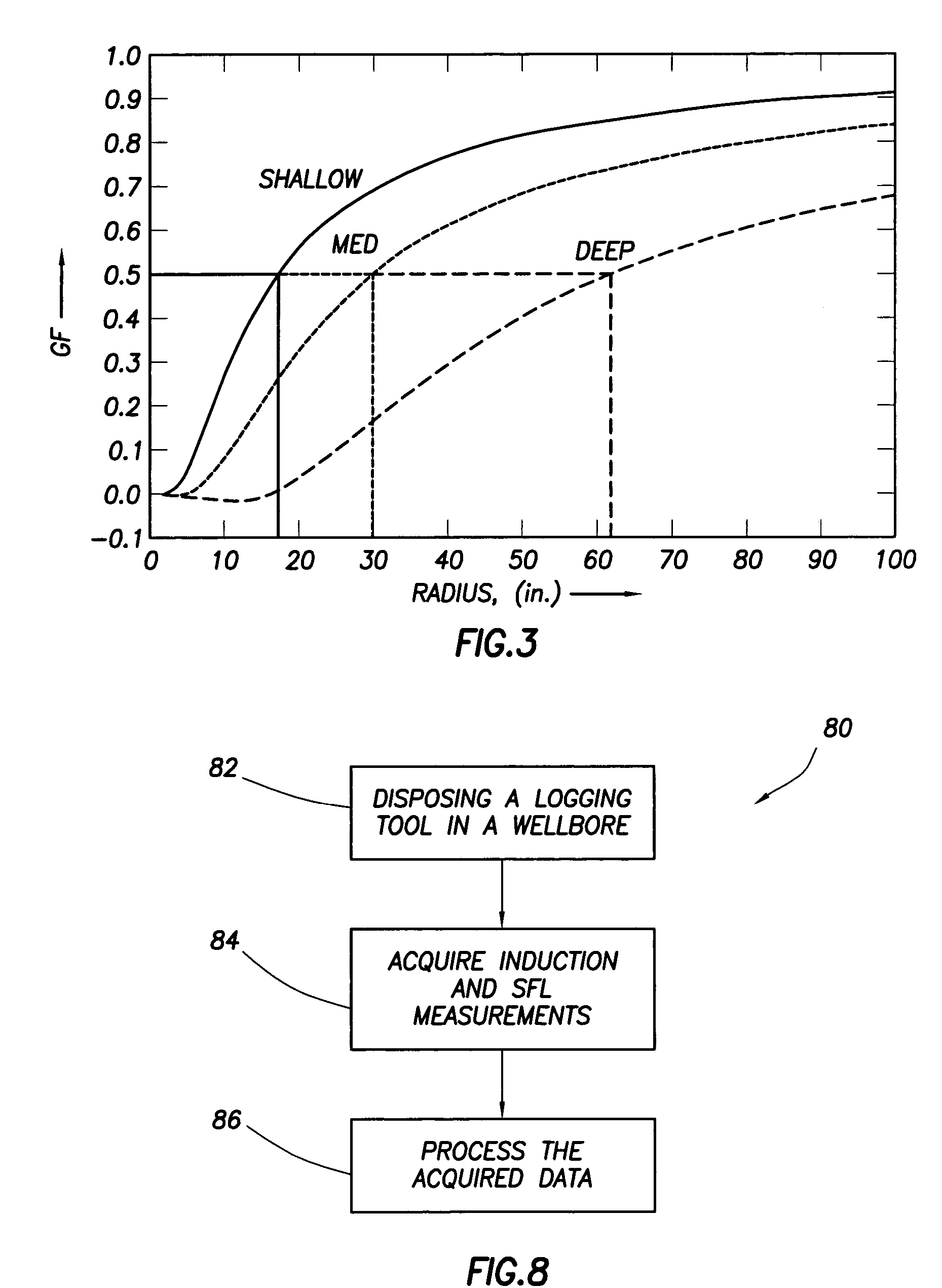
[0034]As noted above, several factors should be taken into consideration in designing an induction tool. These factors include depth of investigation (DOI), resolution, borehole effects, frequency of operation, ...


PUM


Abstract

A well logging tool includes an induction array stack disposed on a mandrel; an electronic module stack disposed adjacent the induction array stack along a longitudinal axis of the well logging tool; and a shallow electrode array arranged on a housing disposed around the electronic module stack, wherein the induction array stack comprises a transmitter antenna, a first receiver antenna, and a second receiver antenna spaced apart from each other along the longitudinal axis of the well logging tool, the second receiver antenna being disposed between the transmitter antenna and the first receiver antenna.

Description

BACKGROUND OF THE INVENTION[0001]1. Field of the Invention[0002]This invention relates to electrical logging apparatus and methods for determining the nature and characteristics of the various sub-surface formations penetrated by a borehole in the earth.[0003]2. Background Art[0004]Various resistivity logging techniques have been used to determine electrical properties of sub-surface formations. One commonly used technique is induction-SFL (spherically focused laterolog) logging. The induction component of the induction-SFL logging measures the resistivity (or its inverse, conductivity) of the formation by inducing eddy currents in the formations in response to an AC transmitter signal. The eddy currents induce secondary magnetic fields that in turn induce a voltage in a receiver antenna. Because the magnitudes of the eddy currents depend on formation conductivities, the magnitudes of the received signal thus reflect the formation conductivities. The SFL component of the induction-S...

Claims


Application Information

Patent Timeline
Patent Type & Authority Patents(United States)
IPC IPC(8): G01V3/28G01V3/20
CPCG01V3/20G01V3/28
Inventor BARBER, THOMAS D.
Owner SCHLUMBERGER TECH CORP
Why Eureka
Try Eureka