Signal transformer and method for operating such a signal transformer

a signal transformer and transformer technology, applied in the direction of electric variable regulation, process and machine control, instruments, etc., can solve the problems of inability to transmit a single primary winding signal on the transformer input side, huge increase in material costs due to the number of signal transformers required, and large number of signal transformers additionally accompanied by an undesirably large space requirement, etc., to achieve low space and material costs, simple manner, and high maintainability

Inactive Publication Date: 2006-05-09
ABB RES LTD
View PDF18 Cites 16 Cited by
  • Summary
  • Abstract
  • Description
  • Claims
  • Application Information

AI Technical Summary

Benefits of technology

[0005]The signal transformer according to the invention has a primary limb and a first secondary limb, a primary winding being provided, which at least partly encloses the primary limb, and a secondary winding furthermore being provided, which at least partly encloses the first secondary limb. Moreover, the primary limb is connected to the first secondary limb. According to the invention, 2n+1 additional limbs are provided, where n=0, 1, 2, 3, . . . , and the additional secondary limbs are connected to the primary limb and the first secondary limb. At least one secondary winding is in each case provided for the additional secondary limbs and for the first secondary limb, the secondary winding at least partly enclosing the respective secondary limb. Furthermore, a control winding is provided for each secondary limb, said control winding at least partly enclosing the respective secondary limb. By virtue of the fact that 2n+1 additional secondary limbs, i.e. an odd number of additional secondary limbs, are provided and at least one secondary winding is in each case provided for the additional secondary limbs and for the first secondary limb, a primary winding signal fed into the primary winding can advantageously be transmitted to all the secondary windings so that a secondary winding signal is present at each output of the secondary windings. Transmission of a single primary winding signal as a plurality of secondary winding signals, i.e. as a number of secondary winding signals corresponding to the number of secondary windings, is thus made possible in a particularly simple manner. Accordingly, only a single signal transformer is required for transmitting a primary winding signal as a plurality of secondary winding signals, as a result of which a simple and cost-effective signal transformer requiring little space and materials can advantageously be achieved.
[0006]Moreover, by means of a control signal being fed into the control winding provided for each secondary limb, the secondary winding signal of the corresponding secondary limb can be switched on or off in a targeted manner, so that, by way of example, maintenance work can be carried out on this secondary limb without having to interrupt the operation of the signal transformer. As a result, it is advantageously possible to realize a signal transformer which is highly maintainable and characterized by a high availability.
[0007]In the in

Problems solved by technology

What is problematic in the case of a signal transformer described above in accordance with GB 2 293 933 A is that this enables only a single primary winding signal present at the primary winding, for example a switch-on signal or a switch-off signal, to be transmitted as a secondary winding signal.
It is thus not possible to transmit a single primary winding signal on the transformer input side as a plurality of secondary winding signals on the transformer output side.
By virtue of the fact that, therefore, only precisely one primary winding signal can be transmitted as a secondary winding signal in the case of a signal transformer described above in accordance with GB 2 293 933 A, when there are a plurality of seconda

Method used


Image

  • Signal transformer and method for operating such a signal transformer
  • Signal transformer and method for operating such a signal transformer
  • Signal transformer and method for operating such a signal transformer

Examples


Embodiment Construction

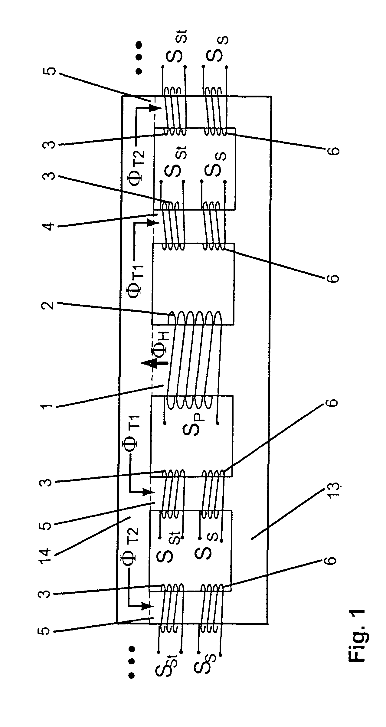
[0018]FIG. 1 illustrates an embodiment of a signal transformer according to the invention. The signal transformer according to the invention has therein a primary limb 1 and a first secondary limb 4. Furthermore, a primary winding 2 is provided, which at least partly encloses the primary limb 1. Furthermore, in accordance with FIG. 1, a secondary winding 6 is provided, which at least partly encloses the first secondary limb 4. Moreover, the primary limb 1 is connected to the first secondary limb 4. According to the invention, an odd number of, i.e. 2n+1 additional secondary limbs 5 are provided, where n=0, 1, 2, 3, . . . . Accordingly, the signal transformer according to the invention has an even number of secondary limbs 4, 5 overall. In accordance with FIG. 1, the additional secondary limbs 5 are connected to the primary limb 1 and the first secondary limb 4. At least one secondary winding 6 is in each case provided for the additional secondary limbs 5 and for the first secondary ...


PUM


Abstract

A signal transformer having a primary limb and a first secondary limb is specified, a primary winding at least partly enclosing the primary limb and a secondary winding at least partly enclosing the first secondary limb and the primary limb being connected to the first secondary limb. Furthermore, 2n+1 additional secondary limbs are provided, where n=0, 1, 2, 3, . . . , and the additional secondary limbs are connected to the primary limb and the first secondary limb. At least one secondary winding is in each case provided for the additional secondary limbs and for the first secondary limb, the secondary winding at least partly enclosing the respective secondary limb. Moreover, a control winding is provided for each secondary limb, said control winding at least partly enclosing the respective secondary limb. Furthermore, a method for operating such a signal transformer and a driver circuit having such a signal transformer are specified.

Description

FIELD OF THE INVENTION[0001]The invention relates to the field of signal transformer technology. It is based on a signal transformer and a method for operating such a signal transformer in accordance with the preamble of claims 1 and 20.BACKGROUND OF THE INVENTION[0002]Signal transformers are nowadays used in a multiplicity of power electronic circuits, in particular in driver circuits for driving power semiconductor switches of converters. In this case, the signal transformer of the driver circuit serves for DC isolation of a signal function generator from the power semiconductor switch to be driven. Such a signal transformer is specified in GB 2 293 933 A, for example, wherein a first signal transformer is provided for DC-isolated transmission of a switch-on signal of the power semiconductor switch and a second signal transformer is provided for DC-isolated transmission of a switch-off signal of the power semiconductor switch. The two signal transformers are customarily embodied w...

Claims


Application Information

Patent Timeline
IPC IPC(8): H01F27/28H01F19/08H01F29/14H01F30/04
CPCH01F19/08H01F29/146H01F27/2804H01F30/04
Inventor JOERG, PIEDERAKDAG, ALPER
Owner ABB RES LTD
Why Eureka
Try Eureka