Planar transformer arrangement

a transformer arrangement and planar transformer technology, applied in the direction of transformer/inductance details, fixed transformers or mutual inductances, inductances, etc., can solve the problems of high-voltage isolation that requires the use of bulky transformers, cumbersome, and all transformers may be negatively affected, so as to improve the electrical coupling between the windings of the planar transformer arrangement

Active Publication Date: 2006-05-09
INFINEON TECH AMERICAS CORP
View PDF9 Cites 16 Cited by
  • Summary
  • Abstract
  • Description
  • Claims
  • Application Information

AI Technical Summary

Benefits of technology

[0010]In accordance with still another exemplary embodiment of the present invention, the magnetic mode interference is canceled without using a differential amplifier circuit. For this purpose, each of the windings of the planar transformer includes two windings connected in anti-series. In this manner, magnetic common mode interference may be automatically canceled without need for external compensating circuitry, such as a differential amplifier circuit.
[0011]In accordance with yet another exemplary embodiment of the present invention, the electromagnetic coupling between the windings of the planar transformer arrangement is improved by providing a magnetic core, for examp

Problems solved by technology

Traditionally, high-voltage isolation has required the use of bulky transformers.
However, such transformers may be costly, cumbersome, and all transformers may be negatively affected by unwanted common-mode noise, such as noise generated by parasitic capacitances and/or an external magnetic field.
These parasitic capacitances result from the close proximity between transformer windings.
However, operation of the transformer may induce the flow of disadvantageous currents within the magnetic core, if the core, for example, contacts the transformer wind

Method used


Image

  • Planar transformer arrangement
  • Planar transformer arrangement
  • Planar transformer arrangement

Examples


Embodiment Construction

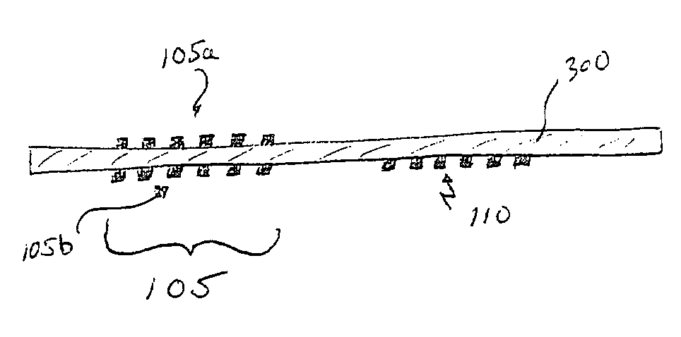
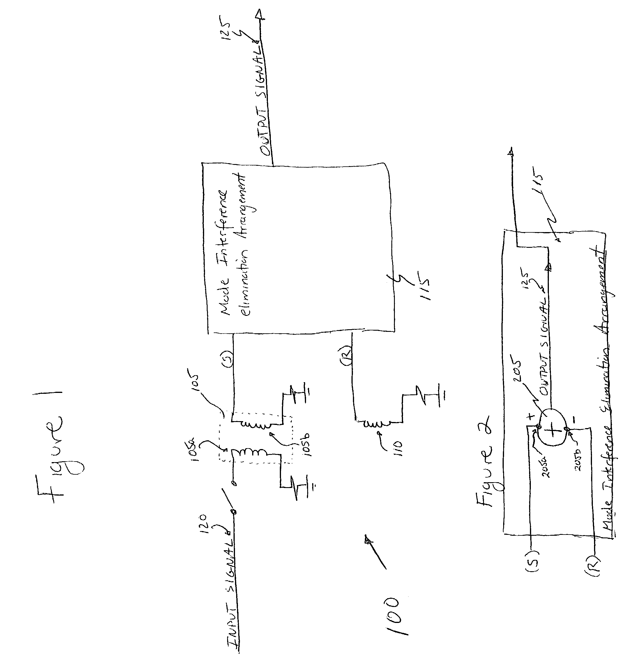
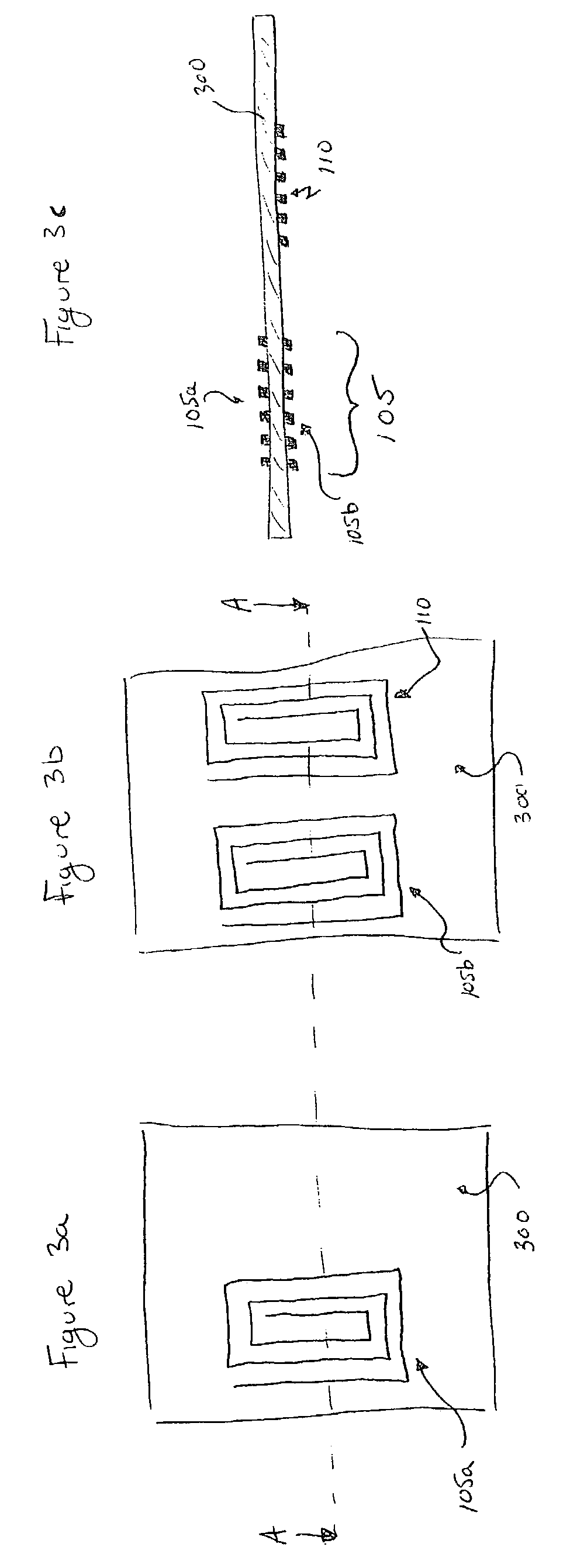
[0023]Referring now to FIG. 1, there is seen a first exemplary planar transformer arrangement 100 according to the present invention. Planar transformer arrangement 100 includes a planar transformer 105 having primary and secondary windings 105a, 105b arranged on respective sides of a planar medium (not shown), e.g., a printed circuit board or an integrated circuit, a single mode detect winding 110 on the same side of the planar medium as the secondary winding 105b, a mode interference elimination circuit 115 electrically connected to the secondary winding 105b of the planar transformer 105 and the single mode detect winding 110.

[0024]The exemplary planar transformer arrangement 100 of FIG. 1 is operable to communicate an input signal 120 applied to the primary winding 105a of the planar transformer 105 to an output signal 125, while providing voltage isolation between the input signal 120 and the output signal 125. Specifically, an input signal 120 applied to the primary winding 10...


PUM


Abstract

A planar transformer arrangement and method provide isolation between an input signal and an output signal. The planar transformer arrangement includes a planar medium having a first layer, a second layer, and a dielectric interlayer arranged between the first and second layers; at least one meandering primary winding arranged on the first layer of the planar medium, a current flow being induced within the primary winding in accordance with the input signal; at least one meandering secondary winding arranged on the second layer of the planar medium, the primary and secondary windings forming a planar transformer, whereby a voltage is induced across the secondary winding in accordance with the current flow within the primary winding; and a mode elimination arrangement configured to produce a compensated voltage by compensating for a common mode interference on the voltage induced across the secondary winding, the mode elimination arrangement being further configured to generate the output signal in accordance with the compensated voltage; wherein the dielectric interlayer of the planar medium provides a voltage isolation between the primary and secondary windings.

Description

RELATED APPLICATIONS[0001]The present application is based on and claims the benefit of U.S. Provisional Application No. 60 / 384,724, filed on May 31, 2002, entitled “PLANAR TRANSFORMER AND DIFFERENTIAL STRUCTURE,” and the present application is based on and claims the benefit of U.S. Provisional Application No. 60 / 420,914, filed on Oct. 23, 2002, entitled “SWITCHING VOLTAGE REGULATOR FOR SWITCH MODE POWER SUPPLY WITH PLANAR TRANSFORMER,” the entire contents of both applications being expressly incorporated herein by reference.FIELD OF THE INVENTION[0002]The present invention relates to a planar transformer arrangement and method for isolating driver circuitry and communication circuitry to eliminate magnetic field interference and parasitic capacitance.BACKGROUND INFORMATION[0003]Transformers are often used in floating gate driver circuits for driving high power / voltage switches, for example, high voltage IGBTs for motor control and other applications. In such an application, a tran...

Claims


Application Information

Patent Timeline
IPC IPC(8): H01F5/00H01F17/00H01F27/28H01F27/32H01F27/34
CPCH01F17/0013H01F27/2804H01F27/323H01F27/345H01F2027/2819H01F2017/0093H01F2019/085
Inventor GIANDALIA, MARCOGRASSO, MASSIMOPASSONI, MARCO
Owner INFINEON TECH AMERICAS CORP
Why Eureka
Try Eureka