Fault location apparatus and procedures in CWDM business applications using wavelength selective OTDR

a wavelength selective otdr and fault location technology, applied in the field of optical communication, can solve the problems of inability to troubleshoot wdm systems, high equipment fixed cost, and inability to penetrate dwdm technology into local applications, etc., to achieve the effect of troubleshooting wdm systems, and otdr that operates on a single wavelength is impractical

Active Publication Date: 2006-05-09
AMERICAN TELEPHONE & TELEGRAPH CO
View PDF2 Cites 42 Cited by
  • Summary
  • Abstract
  • Description
  • Claims
  • Application Information

AI Technical Summary

Benefits of technology

[0008]In accordance with yet another aspect of the invention, the method enables fault diagnosis in a WDM system connecting a plurality of LNS nodes. The method eliminates...

Problems solved by technology

However, this dense WDM (DWDM) technology has not penetrated into local applications for several reasons, primarily including the relatively high costs per circuit arising from the fixed cost of equipment in local applications where the traffic volumes per route are relatively low.
A conventional OTDR that operates on a single specified wavelength is impractical, however, for troubleshooting WDM systems because the multiplexer/demultiplexer equipment have ports that are opaque to light having wavelengths outside their respective passbands.
This is disadvantageous, since some fraction of the known fail...

Method used


Image

  • Fault location apparatus and procedures in CWDM business applications using wavelength selective OTDR
  • Fault location apparatus and procedures in CWDM business applications using wavelength selective OTDR
  • Fault location apparatus and procedures in CWDM business applications using wavelength selective OTDR

Examples


Embodiment Construction

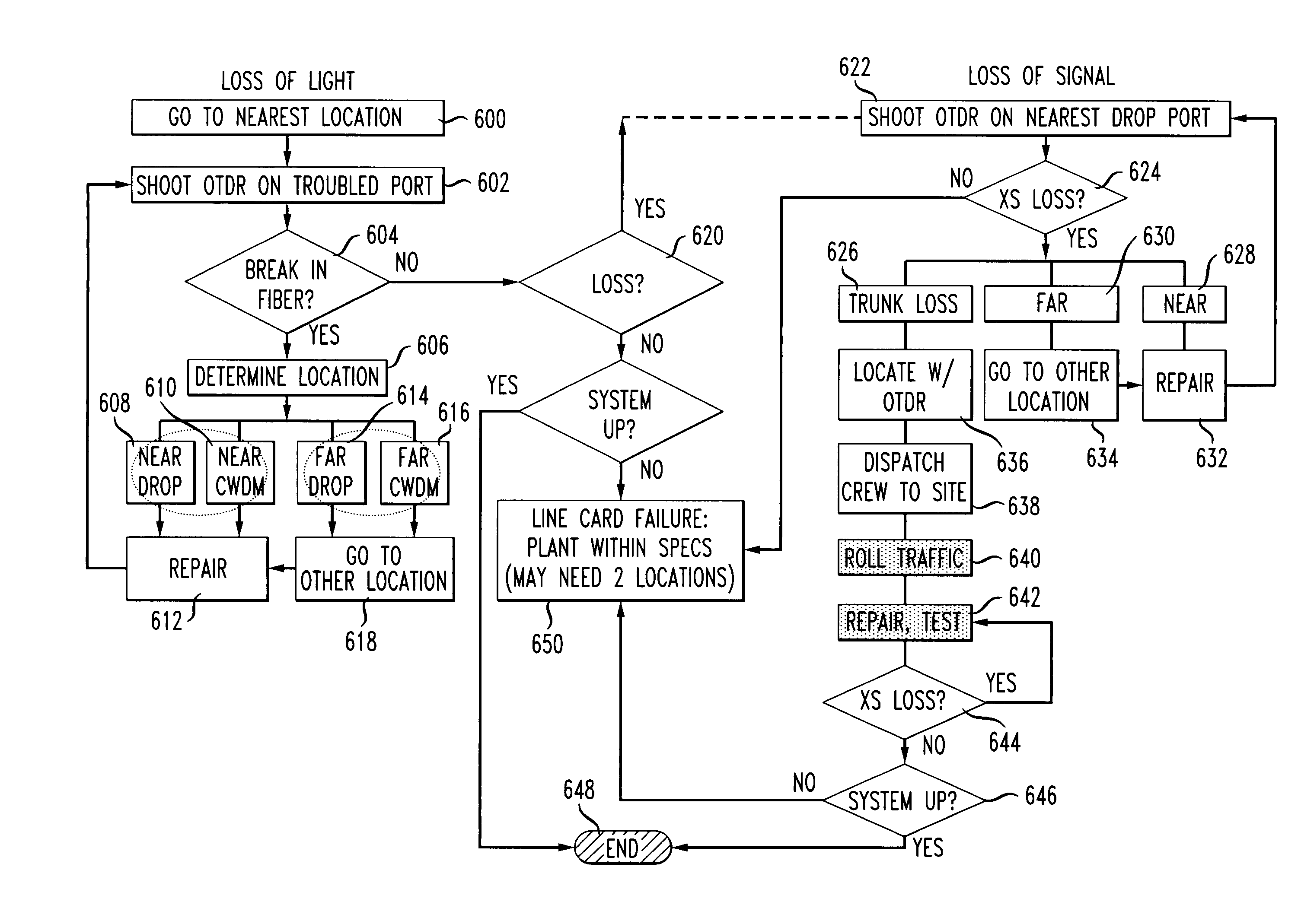
[0022]With reference now to the several views of the drawings, a method is described for verifying and diagnosing optical media connections in WDM systems.

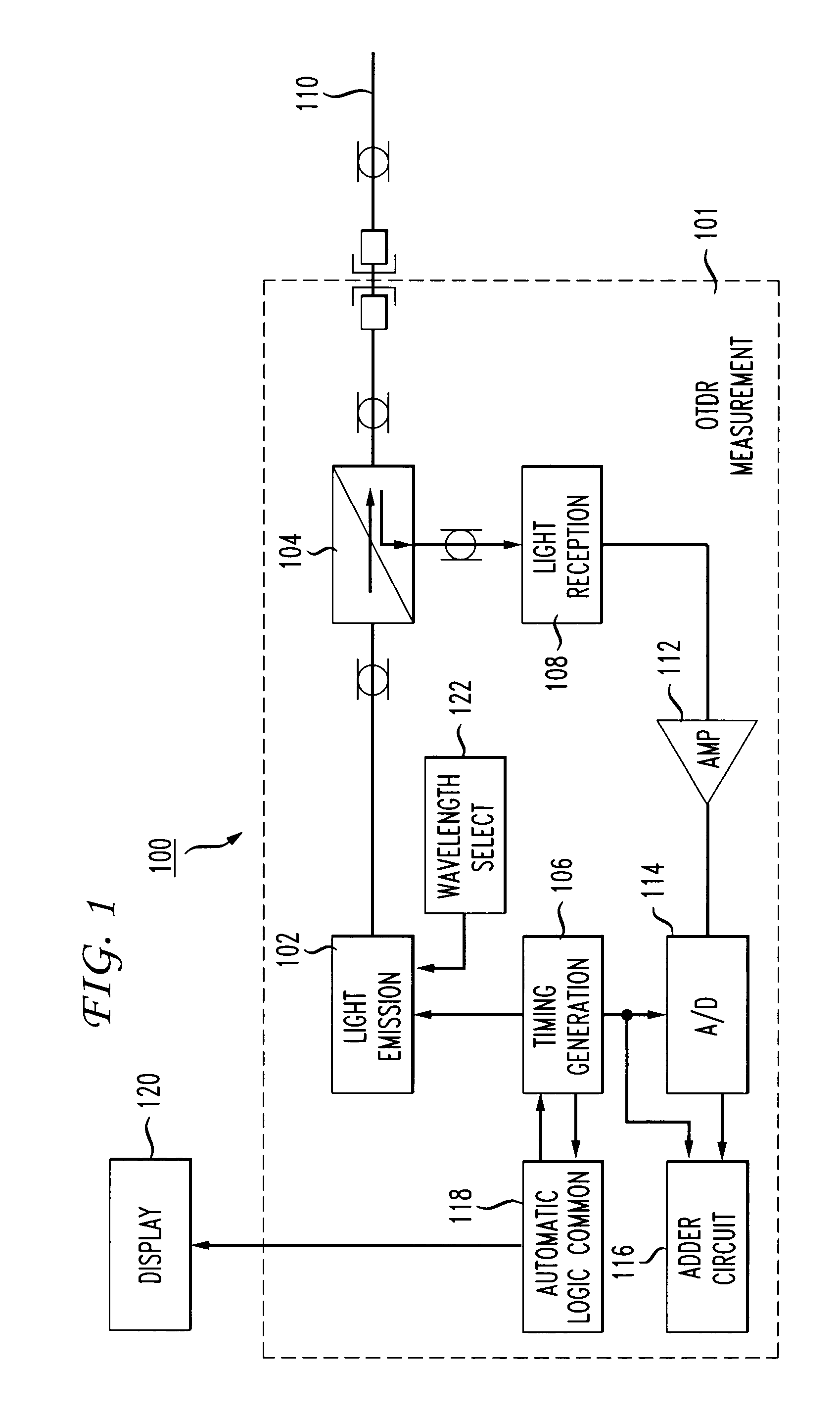
[0023]FIG. 1 is a schematic of an exemplary OTDR 100, which generally comprises an OTDR measurement section 101 including a light emission source 102, optical coupler 104, timing generation section 106, and light reception section 108. The timing generation section 106 communicates a signal to the light emission source 102 to generate an optical pulse, which is incident on an optical fiber generally represented at 110. The optical pulse propagates through the fiber 110, and any reflected or backscattered light is returned through the optical coupler 104 and captured by the light reception section 108. This backscattered light is amplified with a predetermined amplification factor by amplifier 112, and converted to a digital signal by A / D converter 114. In the A / D converter 114, the amplifier output is sampled in a predetermined sa...


PUM


Abstract

A method for verifying fiber connections and diagnosing loss of light or loss of signal conditions in a WDM optical system. The method utilizes an optical time domain reflectometer (OTDR) having user-selectable wavelengths to shoot OTDR traces at a specified wavelength corresponding to an optical data-bearing channel into a selected one of a plurality of optical fiber transmission lines that are connected to a multiplexer that respectively multiplexes a data bearing channel carried on each of the plurality of optical fiber transmission lines onto a trunk, or a demultiplexer that demultiplexes multiplexed data bearing channels from the trunk. The OTDR receives backscattered light from the selected optical fiber transmission line and generates a trace of the backscattered light, thereby enabling a fault location in the WDM optical system to be determined from the trace.

Description

FIELD OF THE INVENTION[0001]The present invention relates generally to optical communications, and more particularly, to an apparatus and method of verifying fiber connections and diagnosing faults in wavelength division multiplexing (WDM) systems using an optical time domain reflectometer (OTDR) having user selectable wavelength capability, in which the set of wavelengths comprises the optical channels in a WDM transmission system.BACKGROUND[0002]Wavelength-division multiplexing (WDM) has been employed in core networks for almost a decade. WDM technology enables signals of multiple wavelengths to be concurrently transmitted over a given optical medium. This has been facilitated by the availability of wideband optical amplifiers that can simultaneously amplify many different wavelengths without distortion. The advantages provided by WDM translate into greater fiber utilization, lower capital expenditures associated with fiber deployment, and reduced costs in repeater stations by eli...

Claims


Application Information

Patent Timeline
IPC IPC(8): G01N21/00
CPCG01M11/3136G01M11/3127
Inventor FRIGO, NICHOLAS J.IANNONE, PATRICK PREICHMANN, KENNETH C
Owner AMERICAN TELEPHONE & TELEGRAPH CO
Why Eureka
Try Eureka