Electronic equipment

a technology of electronic equipment and wiring pattern, applied in the direction of electrical apparatus casing/cabinet/drawer, cooling/ventilation/heating modification, instruments, etc., can solve the problems of increasing heat generation amount and power consumption, and increasing mechanical and physical size. , to achieve the effect of reducing the length of the wiring pattern of the connection-use circuit board

Inactive Publication Date: 2006-05-09
HITACHI LTD
View PDF25 Cites 85 Cited by
  • Summary
  • Abstract
  • Description
  • Claims
  • Application Information

AI Technical Summary

Benefits of technology

[0007]The present invention has been made in view of the problems stated above, and its object is to provide an electronic equipment capable of performing effective cooling operations to thereby enable performance enhancement while increasing the reliability.
[0010]Respective ones of the flow paths may be communicably coupled together. For example, a confluence passage is provided within the duct member for coupling and communicating respective flow paths together to thereby permit cooling air streams or “winds” to meet and combine with each other. With such an arrangement, even when any one of the fans making up each fan module goes down during operation due to malfunction or the like, it is possible to efficiently perform cooling by effectively utilizing the cooling winds from all of the remaining fans with proper operability.
[0012]Furthermore, an open / close valve is provided at each inflow port for allowing a cooling wind from each fan to flow into inside of each flow path and for avoiding reverse flow thereof. The open / close valve may be made of a material having flexibility. Examples of the value having flexibility include a lightweight valve made of a polymeric material (such as rubber or else) having elasticity, which is formed into either a film shape or a thin plate shape. The valve opens due to the pressure of a cooling wind being exhausted from a fan and then allows the cooling wind to flow into a flow path. Upon interruption of the fan, the valve closes due to its own weight or a pressure difference to thereby block an inflow port. Thus it is possible to prevent occurrence of a reverse flow when the fan stops. Additionally, in case the valve is formed into a flat plate-like film shape from an elasticity-rich material, it is preferable to comprise a defense mechanism in such a way as to prevent the valve from changing in shape upon closure thereof to thereby ensure that it hardly escape to outside of the inflow port. An example of this defense mechanism is the one that has a stopper member at the inflow port, which member controls the close position of the valve. For example, the stopper member is preferably designed to offer the capability to support at least an almost central portion of the valve while being formed to have a small area to thereby prevent the inflow port from decreasing in flow path area.
[0020]In one form of the invention, the plurality of openings are provided for reducing the length of a wiring pattern of the connection-use circuit board.

Problems solved by technology

However, the MPU performance improvements would result in increases in heat generation amount and in power consumption.
In addition, from viewpoints of retaining attachment compatibility with conventional products and of space-saving, limitations in size arise in many cases.
More specifically, while the data processing is required to offer higher performance, an increase in mechanical and physical sizes is impermissible.

Method used


Image

  • Electronic equipment
  • Electronic equipment
  • Electronic equipment

Examples


embodiment 1

[0044]1. Overview of Control Unit

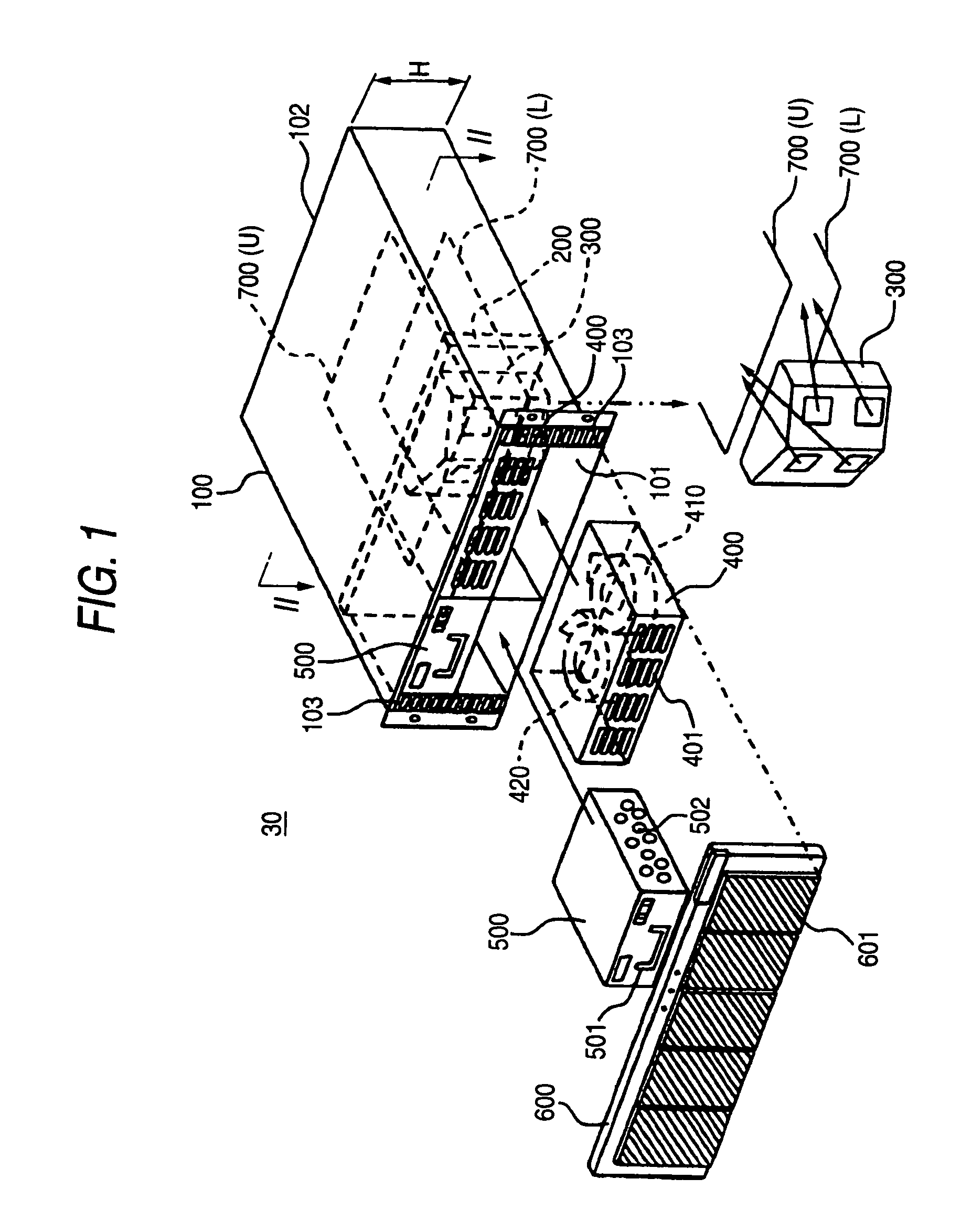
[0045]FIG. 1 is an exploded perspective view showing an overview of the control unit 30. The control unit 30 is a device which controls an operation of disk array apparatus 1 as will be described later. The control unit 30 is generally made up of a chassis 100, back board 200, duct member 300, two fan modules 400, two battery modules 500, decorating door 600, two control modules 700, two interface modules (to be referred to as “I / F” modules hereinafter, a detail of which is shown in FIG. 4) 800, and two power supply modules 900, as will be later described respectively.

[0046]The chassis 100 is made of a metallic material such as stainless steel or the like, which is formed for example into a hollow box-like shape. A front side opening 101 that is positioned on this side in the drawing and a rear side opening 102 that is placed on the far side in the drawing are formed on the both end sides along a longitudinal direction of the chassis 100. The chassis...

embodiment 2

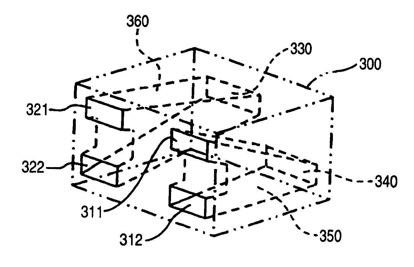
[0158]A second embodiment of the present invention will be explained with reference to FIGS. 17 and 18. A feature of this embodiment lies in that a confluence passage 370 is provided to couple together the lower-side flow path 350 and the upper-side flow path 360 for communication therebetween. FIG. 17 is a perspective view of an internal structure of a duct member 301 in accordance with this embodiment. Although in FIG. 17 the duct member 301 is shown to have a simplified shape for illustration purposes in order to explain the structure of the internal flow path, it actually has an exterior appearance shown in FIG. 6 and is laterally dividable. FIG. 18 is a projection drawing of part of the duct member 301.

[0159]As shown in FIGS. 17–18, the confluence passage 370 is formed within the duct member 301, which passage combines together the lower-side flow path 350 and upper-side flow path 360 for communication therebetween. The confluence passage 370 is positioned on the upstream side ...

embodiment 3

[0162]Next, a third embodiment of the invention will be explained based on FIGS. 19A–19B and 20A–20B. A feature of this embodiment is that an open / close valve 380 is provided at a respective one of the inflow ports 311–312 and 321–322 (referred to hereinafter as “inflow port 311 or the like”) of the duct member 300 (alternatively, this may be the duct member 301). FIGS. 19A–19B include an illustration showing an enlarged cross-sectional view of the part adjacent to a certain one inflow port. FIGS. 20A–B are diagrams each showing an operation state of the valve 380.

[0163]FIG. 19A is a plan view of a stopper member 390 for control of the closed position of the open / close valve 380. The stopper member 390 is attached to each inflow port 311 or the like as shown in FIG. 19B. The stopper member 390 has, for example, a rectangular frame body 391 and at least one supporting portion 392 which is bridged within the frame body 391. An opening 393 is formed between respective support portions ...


PUM

PropertyMeasurementUnit
heightaaaaaaaaaa
lateral widthaaaaaaaaaa
voltageaaaaaaaaaa

Abstract

An object is to effectively cool down an electronic equipment which is face with height limitations and tends to readily increase in heat generation amount to thereby provide the reliability required. The interior of a chassis of a control unit is partitioned by a back board into a front side space and a rear side space. In the rear side space, two control modules are attached so that these are stacked up and down, while two fan modules and a single duct member are attached in the front side space. Each fan module has two fans as built therein. A cooling air stream or “wind” from each fan flows into the lower-side control module through the duct member and others, whereas a cooling wind from the other fan flows into the upper-side control module. Even when either one of the fan modules goes down during operation, it is still possible by using the remaining fan module to cool down the both control modules.

Description

CROSS-REFERENCE TO PRIOR APPLICATION[0001]This application relates to and claims priority from Japanese Patent Application Nos. 2003-270426, filed on Jul. 2, 2003, and 2003-152221, filed on May 29, 2003 the entire disclosure of which are incorporated herein by reference.BACKGROUND OF THE INVENTION[0002]1. Field of the Invention[0003]The present invention relates generally to electronic equipment preferably used for disk array control devices or equivalents thereto.[0004]2. Description of Related Art[0005]In electronic equipment such as for example a control unit for use in disk array apparatus or the like, a micro processing unit (MPU) or else is used to perform processing of a large amount of data at high speeds. Due to this, an increase in inside temperature results in a decrease in processing performance and others so that cooling fans are used to suppress such internal temperature increase (for example, see JP-A-2001-338486).SUMMARY OF THE INVENTION[0006]Although the above-noted...

Claims


Application Information

Patent Timeline
Patent Type & Authority Patents(United States)
IPC IPC(8): H05K7/20G06F1/20G11B33/14
CPCH05K7/20581H05K7/20145
Inventor SUZUKI, KATSUYOSHITAKAHASHI, HIROKAZUHORII, MASAKATSUTATEYAMA, KENICHITAKAHASHI, TAROSUWA, HIROSHIFURUTA, KOUJI
Owner HITACHI LTD
Why Eureka
Try Eureka