Technique for synchronizing clocks in a network

a clock and network technology, applied in the direction of generating/distributing signals, selective content distribution, instruments, etc., can solve the problems of data loss, periodic line errors, data loss,

Active Publication Date: 2006-05-09
RPX CLEARINGHOUSE
View PDF11 Cites 260 Cited by
  • Summary
  • Abstract
  • Description
  • Claims
  • Application Information

AI Technical Summary

Benefits of technology

[0030]In accordance with further aspects of this exemplary embodiment of the present invention, the second differencing element may beneficially initialize the difference signal prior to receiving the first timestamp and the second timestamp.
[0031]In accordance with still further aspects of this exemplary embodiment of the present invention, the apparatus may further beneficially comprise a loop filter for filtering the difference signal such that the second clock signal is synchronized with the first clock signal based upon a filtered difference signal. If such is the case, the loop filter may beneficially initialize the filtered difference signal prior to receiving the first timestamp and the second timestamp.

Problems solved by technology

Two main performance degradation issues come into play when clocks at a transmitter and a receiver are not synchronized.
First, if the physical interfaces along a connection are not synchronized (i.e., not driven by a clocking signal of identical frequency), data can be lost due to buffer overflow or underflow, resulting in periodic line errors.
Second, imperfections in clock synchronization can lead to observable defects on an end service such as bit errors due to alignment jitter when interworking with a plesiochronous digital hierarchy (PDH) or a synchronous digital hierarchy (SDH) network, or frame slips when interworking with a public switched telephone network (PSTN) or an integrated service digital network (ISDN).
IP / Ethernet networks offer essentially an asynchronous transmission service, thus making the synchronization needs of real-time applications difficult to meet in these networks.
Lack of synchronization traceability between TDM equipment interconnected over a packet network may result in frame or byte slips which can affect data integrity.
This offers the best clock quality, but can be expensive since the network requires a PRS and a clock distribution service, except in toll-bypass networks where there is a PRS at each end of the packet network.
The regulatory constraints may also make this approach impractical.
This technique cannot guarantee the bit level integrity of the data unless the transmitter and receiver clocks are synchronized with each other.
Unfortunately, the presence of transmission jitter affects the performance of the clock estimation / compensation process, making the transmitter clock appear faster or slower than it actually is, and ultimately, causing the propagation of some residual jitter to the receiver clock signal.
The presence of even a modest amount of jitter makes the clock recovery problem difficult.
The timestamp method may also be used when user data traverses a number of different networks and it may not be possible to provide a common network clock to transmitting and receiving end-stations.
However, this is not the case in packet networks.
Lastly, the third contributor is due to packet multiplexing and variations in queuing delays in network switches.
If a significant amount of jitter is passed on to the recovered clock, its quality may degrade (i.e., the PLL 30 may not provide a sufficiently stable clock signal).

Method used


Image

  • Technique for synchronizing clocks in a network
  • Technique for synchronizing clocks in a network
  • Technique for synchronizing clocks in a network

Examples


Embodiment Construction

)

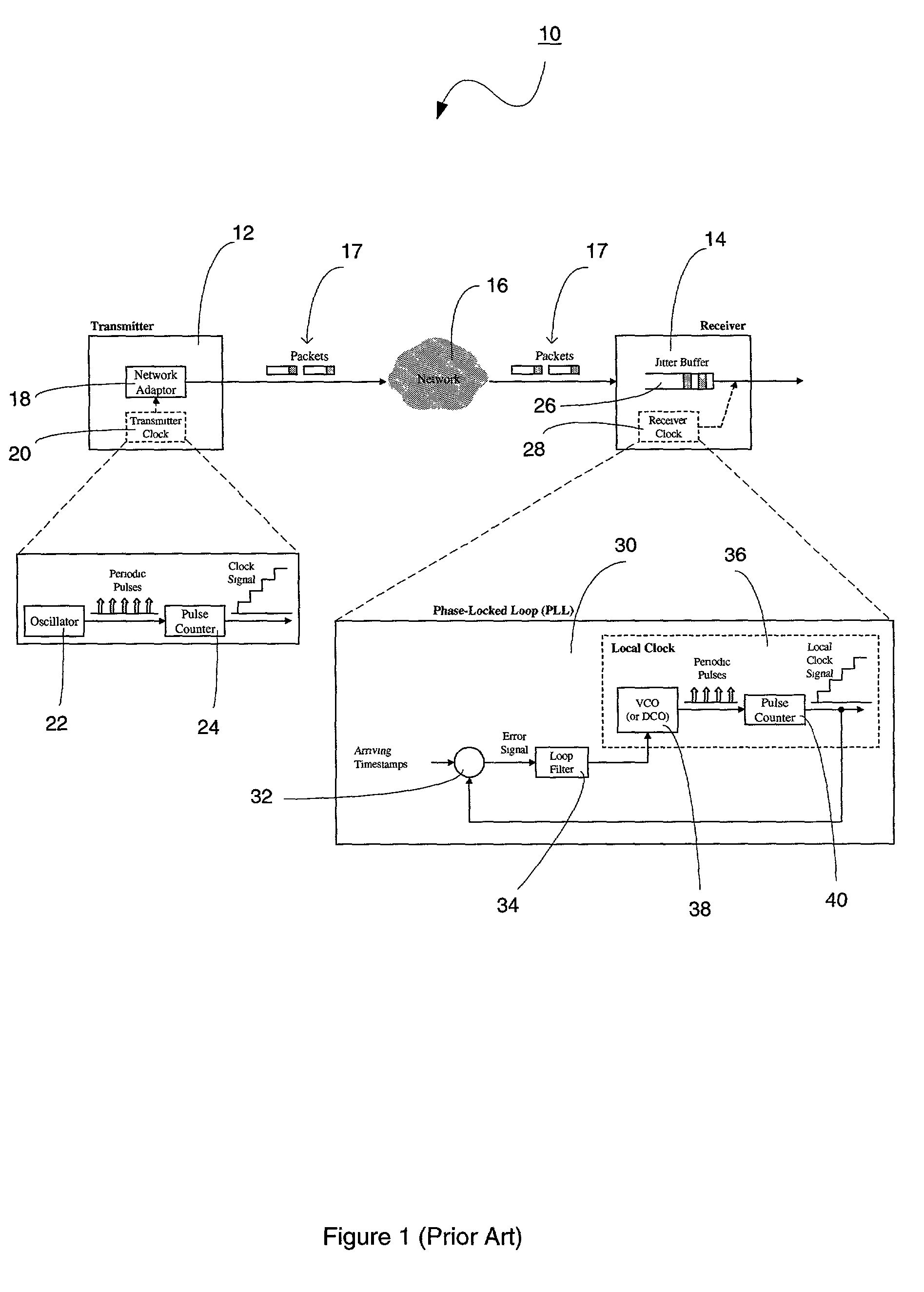
[0053]Referring to FIG. 4, there is shown an improved phase-locked loop (PLL) 50 that uses differences in timestamps to perform clock synchronization in accordance with the present invention. The improved PLL 50 comprises a first delay element 52, a first differencing element 54, a second differencing element 56, a loop filter 58, a digitally controlled oscillator (DCO) 60, a pulse counter 62, a second delay element 64, and a third differencing element 66.

[0054]Similar to FIG. 3, FIG. 4 shows how jitter is introduced (figuratively via summing junction 42) to timestamps that are generated at a transmitter and later received at the improved PLL 50, which is located at a receiver. As indicated above, the introduced jitter is mainly caused by frequency drift between transmitter and receiver clocks, timestamp packetization, and packet multiplexing and variations in queuing delays in network switches.

[0055]It should be assumed that both the transmitter and the receiver have their own tim...


PUM


Abstract

A technique for synchronizing clocks in a network is disclosed. In one exemplary embodiment, the technique may be realized as a method for synchronizing clocks in a network. The method comprises receiving a first timestamp and a second timestamp, each indicating a respective time instance as determined by a first clock signal within the network. The method also comprises measuring a first time interval between the first timestamp and the second timestamp. The method further comprises generating a difference signal representing a difference between the first time interval and a second time interval, and generating a second clock signal based upon the difference signal such that the second clock signal is synchronized with the first clock signal.

Description

CROSS-REFERENCE TO RELATED APPLICATIONS[0001]This patent application claims priority to U.S. Provisional Patent Application No. 60 / 323,125, filed Sep. 18, 2001, which is hereby incorporated by reference herein in its entirety.FIELD OF THE INVENTION[0002]The present invention relates generally to clock synchronization in a network and, more particularly, to an improved phase-locked loop technique for synchronizing clocks in a network using timestamps.BACKGROUND OF THE INVENTION[0003]Clock synchronization in a communication network is the means by which a clock signal is generated or derived and distributed through the network and its individual nodes for the purpose of ensuring synchronized network operation. Herein, clocking refers to a process whereby a timing signal is used by a physical interface of a network device to put data on a transmission media as well as extract data from the transmission media. In other words, clocking at a physical interface of a network device controls...

Claims


Application Information

Patent Timeline
Patent Type & Authority Patents(United States)
IPC IPC(8): G06F1/12H04L7/00H03L7/093H03L7/099H03L7/18H04J3/06
CPCH03L7/093H03L7/0992H03L7/18H04N21/64322H04N21/242H04N21/4305H04J3/0632H04J3/0664
Inventor AWEYA, JAMESOUELLETTE, MICHELMONTUNO, DELFIN Y.FELSKE, KENT E.
Owner RPX CLEARINGHOUSE
Why Eureka
Try Eureka