Cladding system

a technology of cladding system and cladding plate, which is applied in the direction of walls, floors, building components, etc., can solve the problems of mechanical anchor damage, difficult to do, and time-consuming, and achieve the effects of convenient, quick and easy mounting or removal, and great flexibility in construction

Inactive Publication Date: 2006-05-16
CRONOS 2000
View PDF31 Cites 197 Cited by
  • Summary
  • Abstract
  • Description
  • Claims
  • Application Information

AI Technical Summary

Benefits of technology

[0012]Advantageously, in the cladding system of the present invention, each cladding panel is independently demountably secured between a pair of support rails. The cladding panel can be readily, easily and quickly mounted on or removed from the support rails. This system also provides great flexibility in construction. The cladding panels can be mounted on the rails independently and out of any particular sequence so that there are no construction delays providing that there are some cladding panels available which can be mounted in any order on the rails. A further advantage is that the cladding panels can be mounted on the rails from the top of the building downwardly to the base of the building. This means that scaffolding required for are completed moving downwardly from the top, thus providing a cost saving as the scaffolding is usually hired as needed for use on a building site.
[0013]In a particularly preferred embodiment, the bottom of each cladding panel is supported along substantially all of its length up the lower rail. This provides good support for the cladding panel. Also, providing it is ensured that the lower rail is horizontal, all the cladding panels in a row can be dropped onto the rail and they will be level. This facilitates speedy construction.
[0014]In a preferred embodiment, the rails are mounted upon a plurality of spaced-apart vertical mullions having associated anchor means for supporting each mullion in an upright orientation on the building structure. Thus conveniently, once the mullions are in place, the cladding panel support rails may be mounted on the mullions with any desired spacing between each row of rails. Further, in many cases, it will be possible to mount the mullions directly to the floors of the building structure which may mean it is not necessary to build a brick or block wall between the floors, again providing a saving in both time and cost.
[0018]In a further embodiment, a reentrant slot is provided along a face of the mullion for reception of a mounting bolt having a head and a shank, the head being slidably captured within the slot with the shank projecting outwardly of the slot for attachment to the mounting support for the mullion. This conveniently provides for ease of securing the mullions on the mounting support such as the anchor bracket as the mounting bolt can be slid along the slot for alignment with the anchor bracket. Typically, the anchor bracket has a slot for reception of the mounting bolt which may be open-ended to facilitate engagement of the bolt in the slot

Problems solved by technology

With this system, if the cladding panels need to be removed for replacement or access, for example, it is usually very difficult to do so and typically the mechanical anchors are damaged in the process.
As can be appreciated, this is somewhat tedious and time consuming.
A further disadvantage of the sequential construction methods is that if during construction the next required cladding panels are not immediately available on site, the construction of the facade comes to a halt with consequent construction delays and added cost.

Method used


Image

  • Cladding system
  • Cladding system
  • Cladding system

Examples


Embodiment Construction

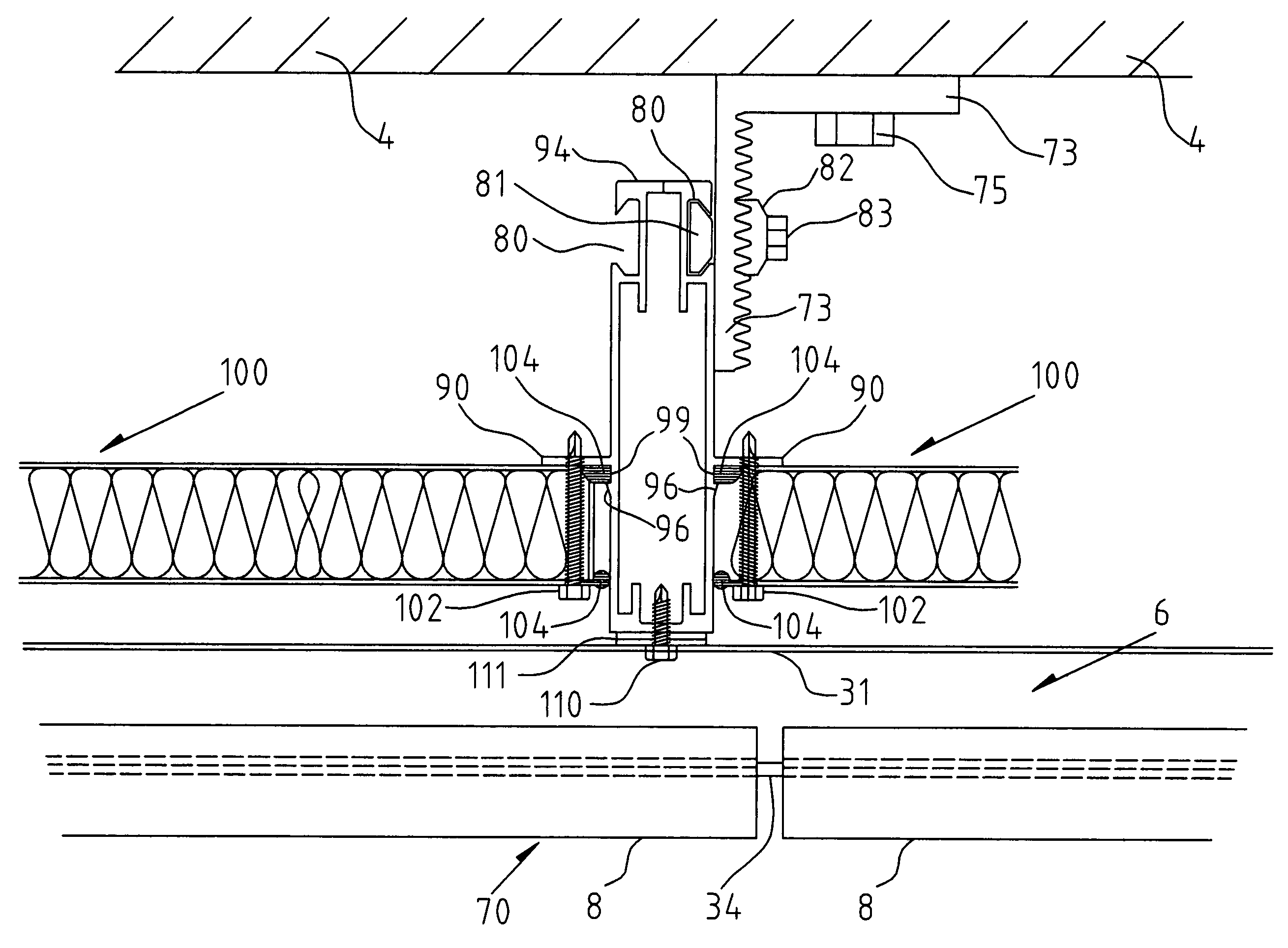
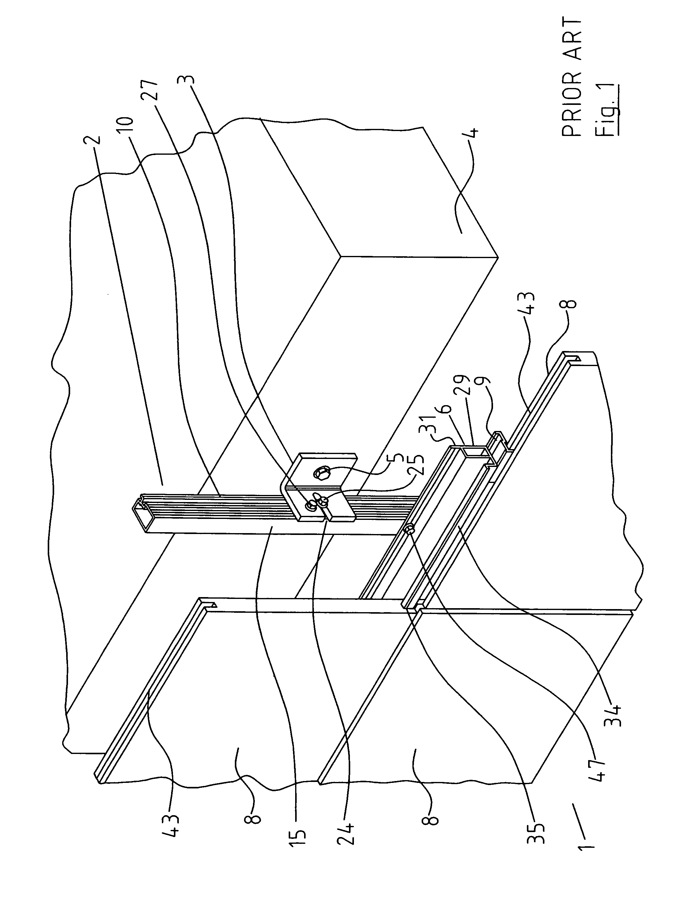
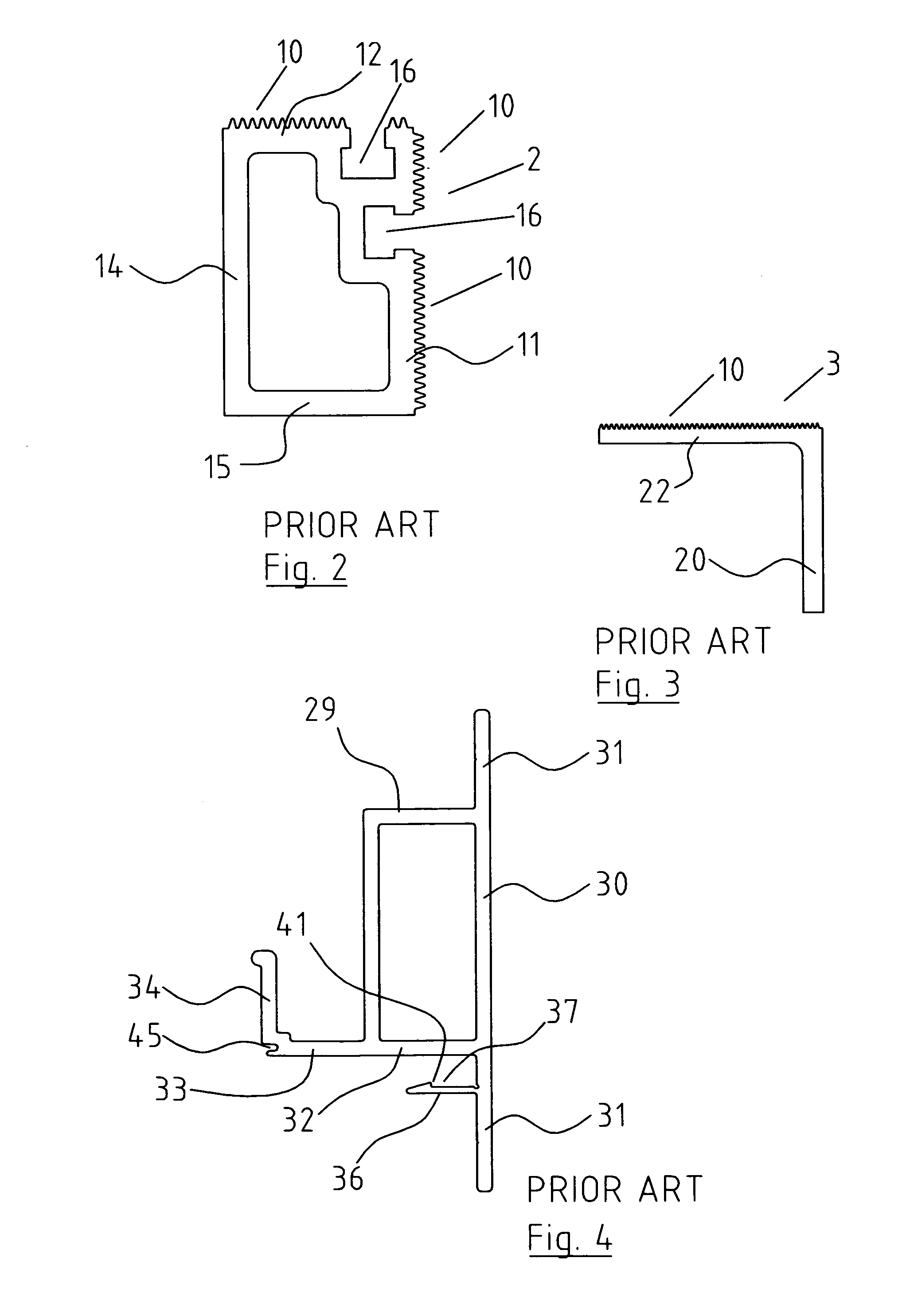
[0044]Referring to the drawings, there is illustrated a cladding system according to the invention, indicated generally by the reference numeral 1. The cladding system 1 comprises a plurality of upright mullions 2 secured to an outside of a building by means of anchor brackets 3, shown in FIG. 1 secured to a floor 4 of the building by means of an anchor bolt 5. The mullions 2 are mounted at spaced intervals along an exterior of the building as best seen in FIG. 15. A number of horizontal cladding panel support rails 6 are mounted on the mullions 2 forming vertically spaced-apart rows of cladding panel support rails 6. Stone cladding panels 8 are mounted between each pair of vertically adjacent rows of panel support rails 6. A bottom of the cladding panel 8 seats on a lowermost rail 6 and a top of the cladding panel 8 is secured to the associated uppermost rail 6 by means of retaining clips 9. Typically, two retaining clips 9 are provided for each panel 8. The mullions 2, anchor brac...


PUM


Abstract

A stone cladding system for building has a support frame formed by a plurality of spaced-apart upright mullions fixed to an exterior of a building by anchor bracket's with a number of horizontal cladding panel support rails mounted in vertically spaced apart rows on the mullions. Each stone cladding panel is mounted between at adjacent pair of vertically spaced-apart rails with a bottom of the cladding panel seated on the lowermost rail and a top of the cladding panel secured to the uppermost rail by a pair of retaining clips. A bottom of each stone cladding panel is fully supported along its length by the lowermost rail.

Description

BACKGROUND OF THE INVENTION[0001]1. Field of the Invention[0002]The invention relates to a cladding system, and in particular to a cladding system for mounting stone cladding panels on an exterior of a building to form the facade of the building.[0003]2. Description of the Prior Art[0004]It is well known to provide stone cladding systems for buildings, particularly relatively large buildings, office blocks and the like, comprising a plurality of store cladding panels secured to the building structure to form a wall by a mounting means engagable between the building structure and each panel. The cladding panels thus form the facade of the building. A known mounting means comprises an anchoring system which requires a brick or concrete wall to which mechanical anchors for each cladding panel are attached or embedded. The anchors fix the stone cladding panels in two load points at a bottom of each stone cladding panel and two restraint points at a top of the stone cladding panel. With ...

Claims


Application Information

Patent Timeline
Patent Type & Authority Patents(United States)
IPC IPC(8): E04B2/88E04F13/08
CPCE04F13/0808
Inventor MORENO, ROLANDO
Owner CRONOS 2000
Why Eureka
Try Eureka