Square ultra thrust reverser system

a reverser system and thrust technology, applied in the direction of machines/engines, jet flaps, transportation and packaging, etc., can solve the problems of affecting the performance of aircraft in various modes of operation, affecting the efficiency of aircraft, and allowing leakage of internal engine gas flow, so as to reduce the possibility of exhaust gas deflection laterally

Active Publication Date: 2006-05-16
OSMAN MEDHAT A
View PDF3 Cites 16 Cited by
  • Summary
  • Abstract
  • Description
  • Claims
  • Application Information

AI Technical Summary

Benefits of technology

[0009]The invention comprises a rectangular / trapezoidal target doors for a thrust reverser system for jet engines. The rectangular / trapezoidal doors provide a relatively flat surface configuration facing the incoming exhaust gases, which in turn help deflect the exhaust gases forward in a more uniform fashion, thereby reducing the possibility of deflection of exhaust gases laterally thereby resulting in some of the exhaust gases / plumes impinging on the aircraft surfaces.
[0010]The side surfaces of the rectangular / trapezoidal doors, act as a strong buffer blocking lateral plumes, thereby minimizing the possibility of impingement on the aircraft surfaces and keeping the majority of the reverse exhaust flow contained by the doors to exert forward decelerating action.
[0014]The actuators may be connected to a pressure booster system to minimize their size. In preferred embodiments the tailpipe comprises a corrugated body. These body corrugations include annularly structured ridges or hats and axially structured depressions or blisters formed with on or in the tailpipe skin. Preferably, the actuators attach to the tail pipe so as to be located in the axial body depressions, and portions of the actuator linkage attach to annular ridge corrugations of the tailpipe body. Acoustical material may be attached over the surface of the tailpipe. In other configuration, four actuators, one at each corner of the door, are used to drive the target doors, thereby eliminating the need for axial body depressions in the tailpipe and eliminating a portion of the actuation linkages.

Problems solved by technology

However, the protrusion of the actuation mechanism into the free air stream surrounding the reverser system, or engine nacelle, has the disadvantage of possibly incurring significant external drag which can penalize aircraft performance in various modes of operation and higher weight penalty.
The single-pivot design has the disadvantage of possibly permitting leakage of the internal engine gas flow between the stowed doors and the tailpipe.
Exhaust flow leakage through the door / tailpipe system, do adversely impact engine thrust performance, fuel consumption and overall aircraft performance.
Exhaust plumes from both of the aforementioned conventional reverser designs are known to sometimes affect the aircraft control surface during reverse thrust operation.
Those additional external surfaces, mandated by considerations of compatibility and systems integration of the reverser with the aircraft, add further cost, weight, potential drag and vibration.
The housing design, in general, for the reverser system, including the actuators and the associated operating mechanism, can adversely affect the external air flow around the tailpipe causing external drag (due to the protrusion of reverser mechanisms in the free air stream around the nacelle thereby causing excessive drag during flight as in the case of the conventional four bar design.
Conventional single pivot reverser designs have the potential for significant flow leakage between such doors and the rest of the tailpipe.
This defect is compounded by a further inability of that design to control the tailpipe exit area which adversely affects forward thrust.
These two defects of this particular conventional housing design severely affect the engine's fuel consumption and performance, penalizing the aircraft's overall performance and range.
On the other hand, excessive drag during flight incurred by the other conventional four bar housing design also penalizes the aircraft's overall performance and range.
Conventional construction techniques for target type thrust reverser components, single pivot or four bar, rely heavily on riveting together individual details and subassemblies of hardware, such as frames, inner skin, outer skin and other detail parts, A multitude of pieces of hardware and the extensive use of riveting increases the system weight as well as development, tooling and manufacturing costs.
These aspects of design are adversely reflected in the aircraft's gross weight, payload, performance and cost of operation.

Method used


Image

  • Square ultra thrust reverser system
  • Square ultra thrust reverser system
  • Square ultra thrust reverser system

Examples


Embodiment Construction

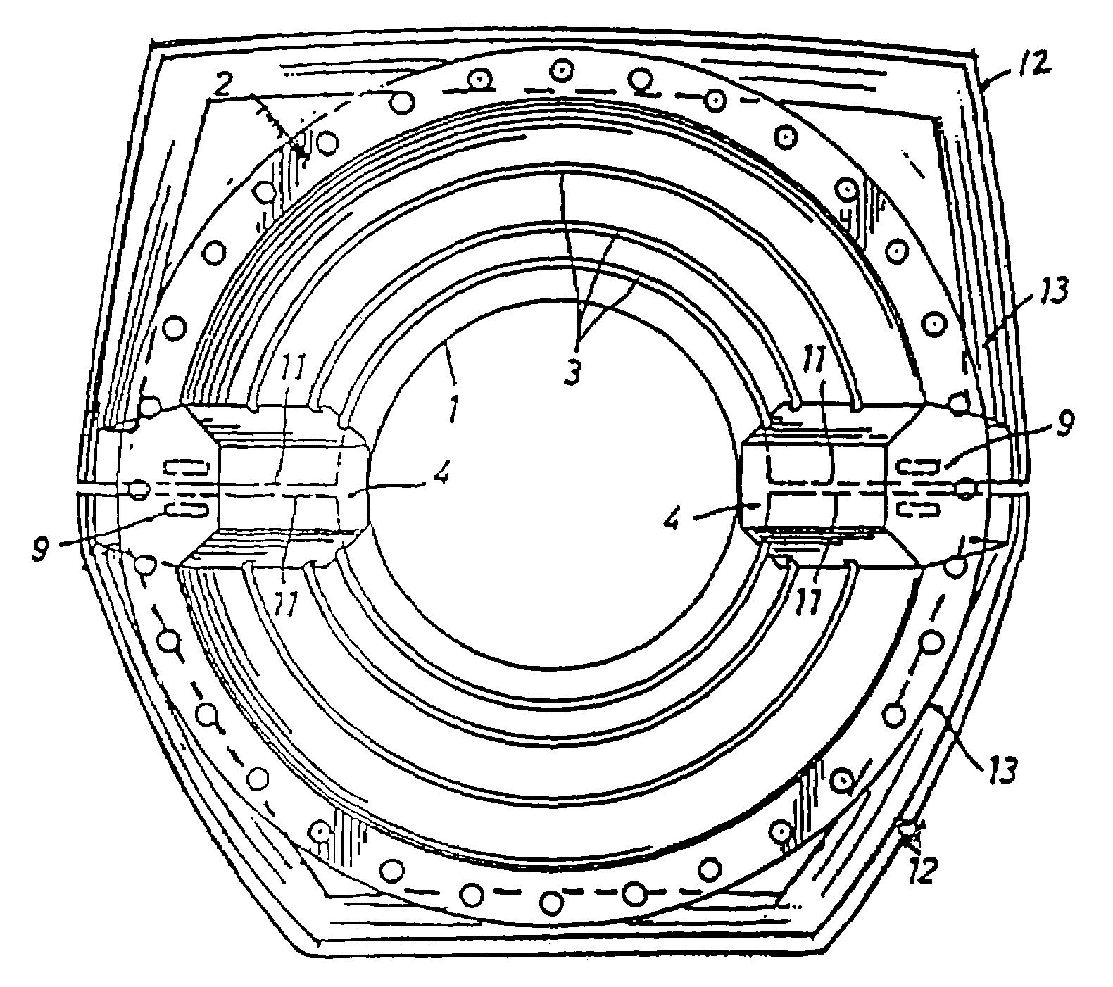
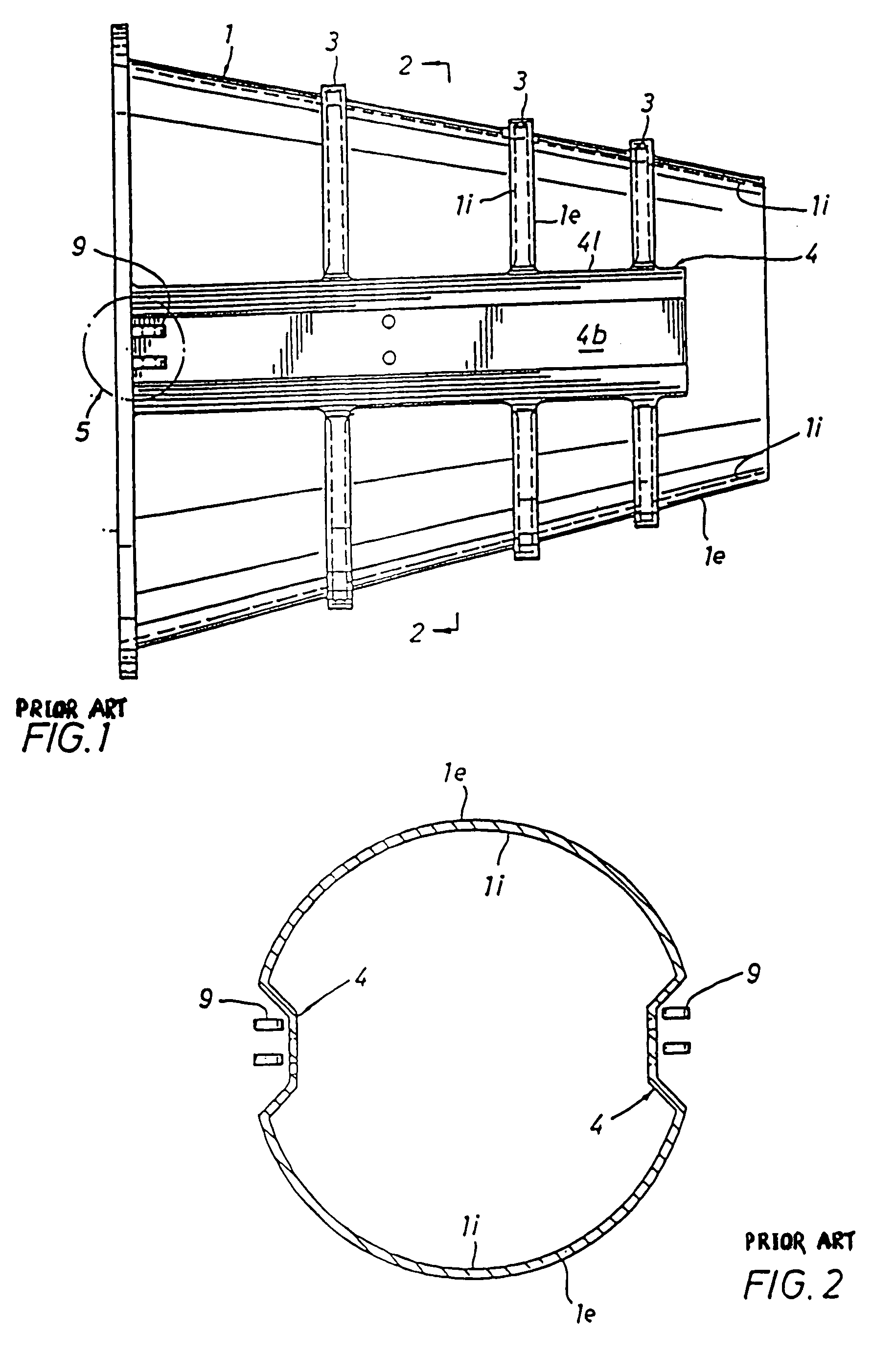
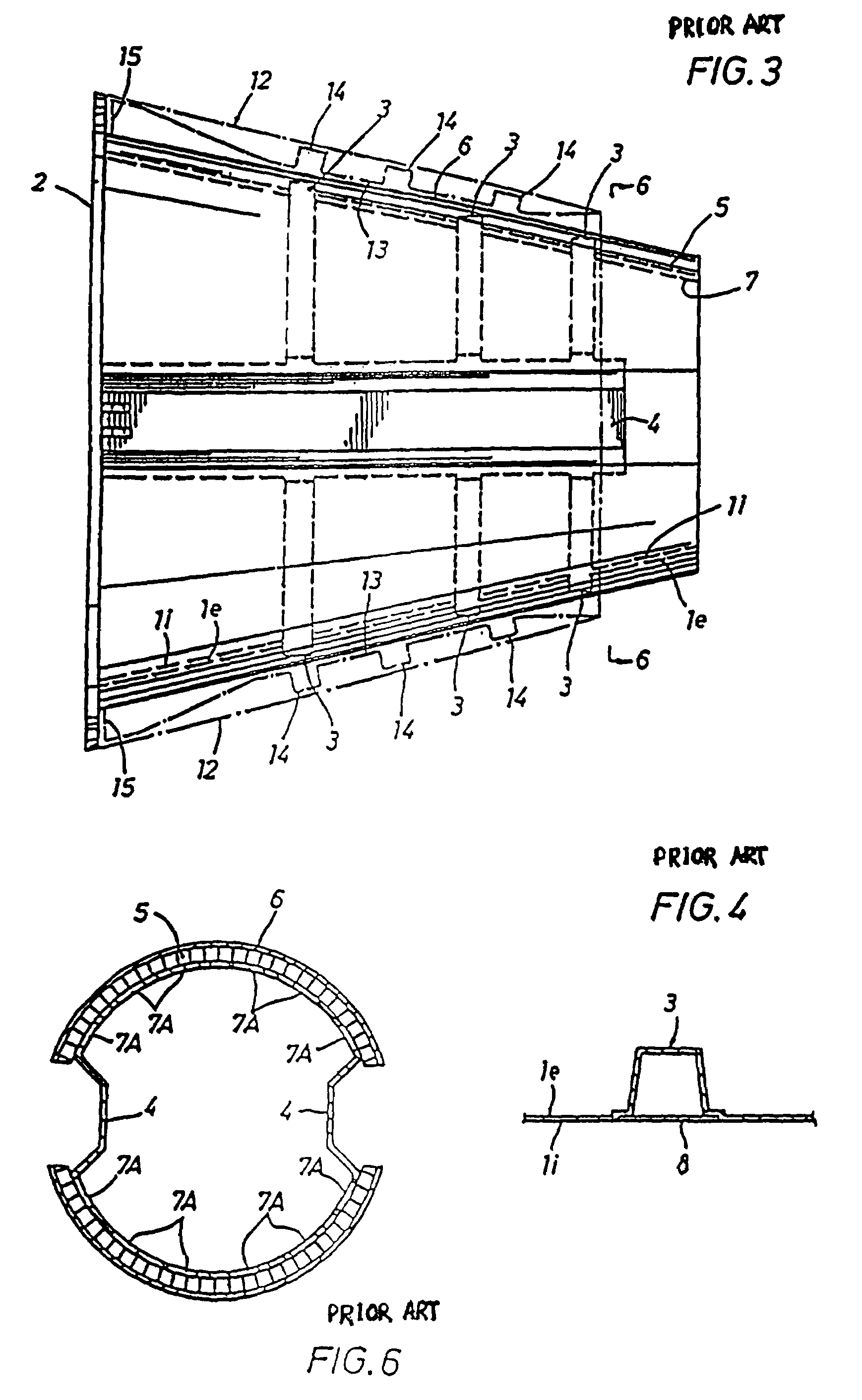
[0041]The design concepts included in preferred embodiments of the thrust reverser system include an integrally constructed exhaust tailpipe best illustrated in FIG. 1E. The integrally constructed corrugated exhaust tailpipe 1 acts as the main structure carrying the various thrust reverser system components and loads. The thrust reverser loads (in the reverse mode) are transmitted through the tailpipe 1 to the engine bulkhead (not shown), to be bolted to a tailpipe attachment flange 2.

[0042]As illustrated in FIGS. 1–11, the integral corrugation construction of tailpipe 1 includes hats or ridges 3, which comprise annular corrugations sometimes referred to as ribs, which can be pressed into the tailpipe material or attached externally to the tailpipe skin, and internal axial blisters or depressions 4, located on each side of tailpipe 1. This integral corrugated design form a cage structure that permits the tailpipe itself to transmit reverse thrust loads directly, in lieu of requiring...


PUM


Abstract

A thrust reverser system for jet engine comprising a tailpipe, Square / trapezoidal clamshell doors and actuators, wherein the tailpipe and clamshell doors may be corrugated, the corrugations can be mating, the actuators may be situated out of the external free air flow, the doors may be stowed out of contact with internal engine gas flow and that may include a tail pipe a fairing having a movable section.

Description

FIELD OF THE INVENTION[0001]This invention relates to thrust reverser systems for aircraft jet engines, based on the ULTRA THRUST REVERSER SYSTEM U.S. Pat. No. 5,615,834. This patent relates to Applicant's Disclosure Document filed Mar. 27, 2000, application No. 60 / 192,337.BACKGROUND OF THE INVENTION[0002]Thrust reverser systems are used to decelerate a jet aircraft, and in particular to slow it down after landing, to slow it down during taxiing, and to aid it to back-up from a tight spot or a gate if needed. Reversing the exhaust jet flow from the engines provides the desired deceleration, especially on short runways, and slows down the aircraft to a safe taxiing speed thereby allowing the pilot to use the brakes on the taxiways.[0003]Previous designs such as U.S. Pat. Nos. 2,968,150 and 3,610,534, sometimes referred to as four bar designs, the thrust reverser is built around the exhaust tailpipe. However, the protrusion of the actuation mechanism into the free air stream surroundi...

Claims


Application Information

Patent Timeline
Patent Type & Authority Patents(United States)
IPC IPC(8): F02K3/02F02K1/60F02K1/70F02K1/76
CPCF02K1/60F02K1/70F02K1/766F05D2250/61Y02T50/671F05D2250/13Y02T50/60
Inventor OSMAN, MEDHAT A.
Owner OSMAN MEDHAT A
Why Eureka
Try Eureka