Spray coolant reservoir system

a technology of spraying and reservoirs, applied in the direction of lighting and heating apparatus, semiconductor/solid-state device details, domestic cooling apparatus, etc., can solve the problems of affecting the thermal management of electronic devices, affecting the efficiency of modern high-end electronics, and excess coolant can also directly affect and damage electronic components, so as to achieve the effect of increasing the efficiency and performance of spraying thermal management systems

Active Publication Date: 2006-05-16
PARKER INTANGIBLES LLC
View PDF41 Cites 40 Cited by
  • Summary
  • Abstract
  • Description
  • Claims
  • Application Information

AI Technical Summary

Benefits of technology

[0011]In view of the foregoing disadvantages inherent in the known types of spray thermal management systems now present in the prior art, the present invention provide

Problems solved by technology

Conventional dry thermal management technology (e.g. fans, vents) simply is not capable of efficiently cooling modern high-end electronics.
One problem with conventional spray technology is that excess coolant is often times retained within the spray chamber to ensure adequate coolant return flow to the pump and to compensate for any coolant leakage.
This excess coolant can interfere with the thermal management of electronic devices within the spray chamber.
In addition, this excess coolant can also directly impact and damage the electronic components during attitude changes, deceleration and acceleration of the spray chamber.
Another problem with conventional spray technology is that prior to accessing the spray chamber the coolant must be drained which can lead to contamination and coolant loss.
A further problem with conventional spray technology is that during acceleration, deceleration and attitude change, temporary coolant l

Method used


Image

  • Spray coolant reservoir system
  • Spray coolant reservoir system
  • Spray coolant reservoir system

Examples


Embodiment Construction

A. Overview

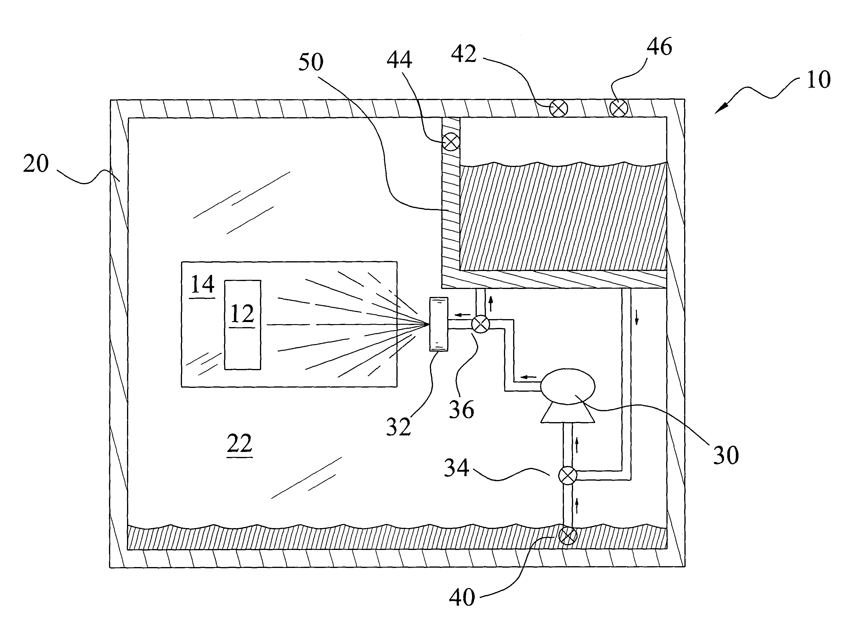
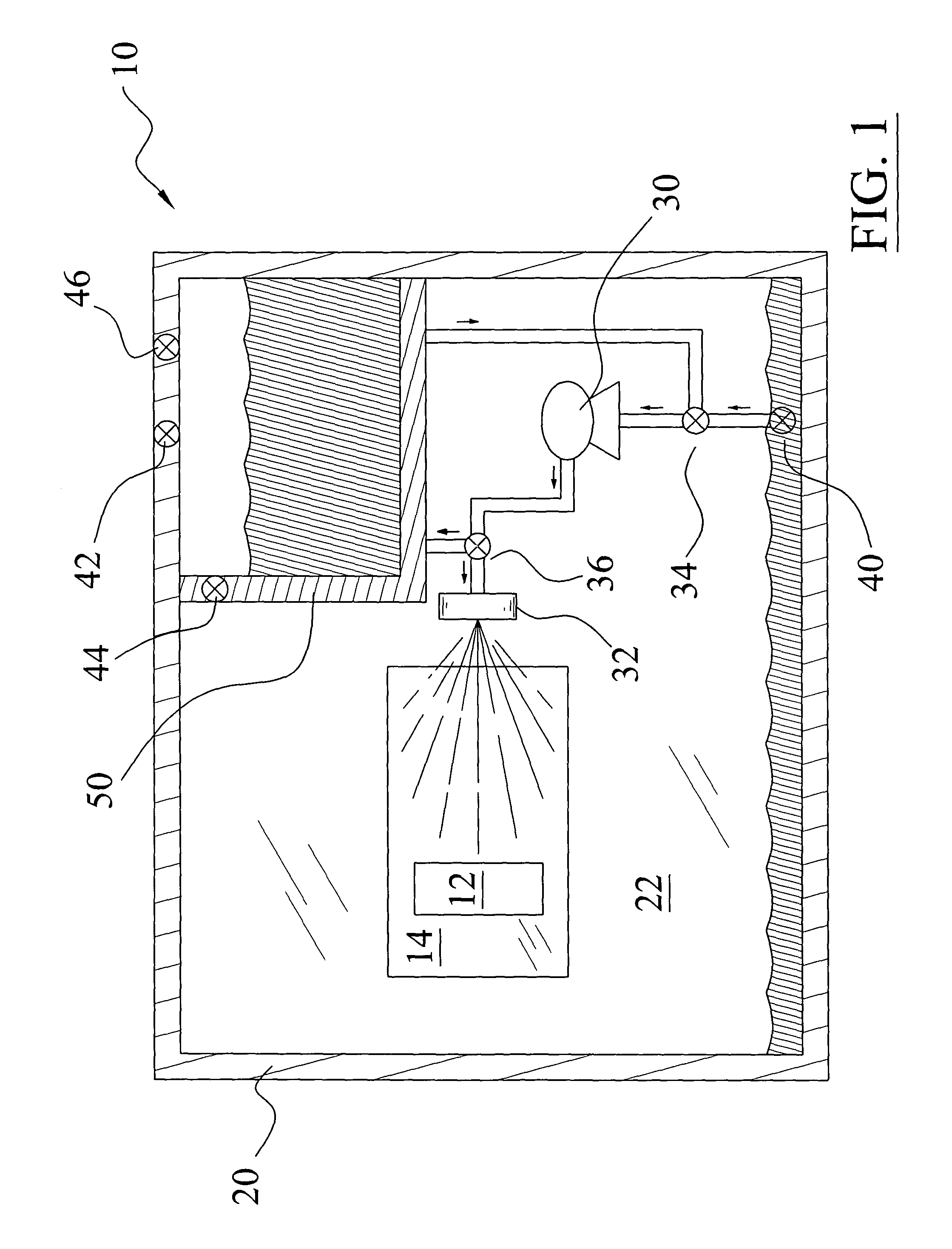
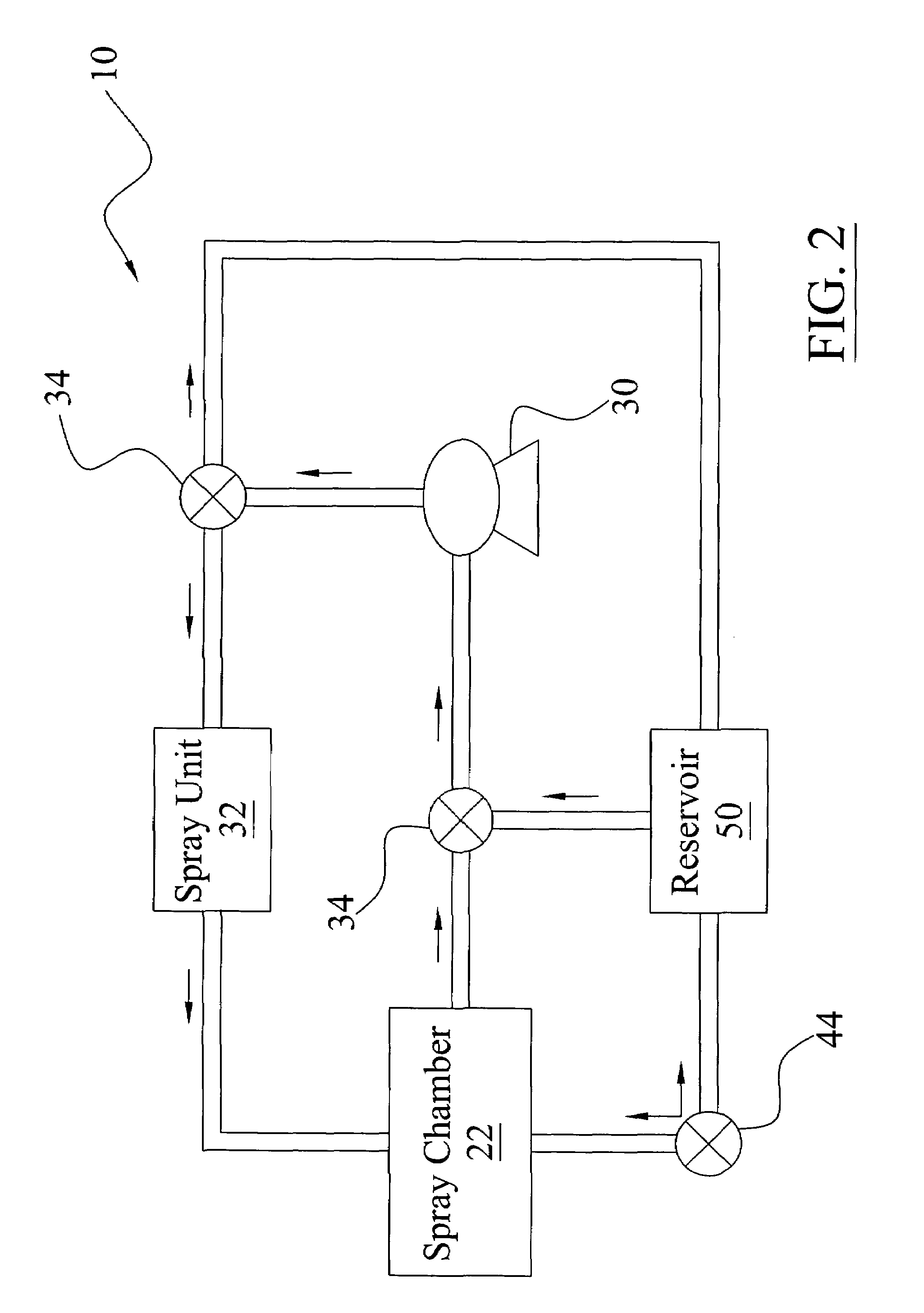
[0040]Turning now descriptively to the drawings, in which similar reference characters denote similar elements throughout the several views, FIGS. 1 through 10 illustrate a spray coolant reservoir system 10, which comprises a reservoir 50 capable of storing a volume of coolant, a chassis 20 with a spray chamber 22, a pump unit 30, an intake valve 34 fluidly connected to the pump unit 30 for providing coolant from the reservoir 50 or the spray chamber 22, an output valve 36 fluidly connected to the pump unit 30 for controlling coolant flow from the pump unit 30 to either the spray unit 32 or the reservoir 50. The reservoir 50 preferably includes a vent port 42, a fill port 46, and a chamber port 44. The chamber port 44 is fluidly connected to the spray chamber 22 for allowing control of the internal pressure within the spray chamber 22.

B. Chassis

[0041]As shown in FIGS. 1, 3 through 6 of the drawings, the chassis 20 may have various shapes, structures and configurations. Th...


PUM


Abstract

A spray coolant reservoir system for increasing the efficiency and performance of a spray thermal management system. The spray coolant reservoir system includes a reservoir capable of storing a volume of coolant, a chassis with a spray chamber, a pump unit, an intake valve fluidly connected to the pump unit for providing coolant from the reservoir or the spray chamber, an output valve fluidly connected to the pump unit for controlling coolant flow from the pump unit to either the spray unit or the reservoir. The reservoir preferably includes a vent port, a fill port, and a chamber port. The chamber port is fluidly connected to the spray chamber for allowing control of the internal pressure within the spray chamber.

Description

CROSS REFERENCE TO RELATED APPLICATIONS[0001]Not applicable to this application.STATEMENT REGARDING FEDERALLY SPONSORED RESEARCH OR DEVELOPMENT[0002]Not applicable to this application.BACKGROUND OF THE INVENTION[0003]1. Field of the Invention[0004]The present invention relates generally to spray thermal management systems for thermally managing electronic devices and more specifically it relates to a spray coolant reservoir system for increasing the efficiency and performance of a spray thermal management system.[0005]2. Description of the Related Art[0006]Modern electronic devices have increased thermal management requirements. Conventional dry thermal management technology (e.g. fans, vents) simply is not capable of efficiently cooling modern high-end electronics.[0007]Spray thermal management technology is being adopted today as the most efficient option for thermally managing electronic systems. U.S. Pat. No. 5,220,804 entitled High Heat Flux Evaporative Spray Cooling to Tilton ...

Claims


Application Information

Patent Timeline
IPC IPC(8): F25D23/12
CPCH01L23/4735H05K7/20345H01L2924/0002H01L2924/00
Inventor KNIGHT, PAUL A.
Owner PARKER INTANGIBLES LLC
Why Eureka
Try Eureka