
Wind power generator with multiple rotary wings

a technology of wind power generator and rotary wing, which is applied in the direction of wind power generation, wind motor with parallel air flow, liquid fuel engine components, etc., can solve the problems of large amount of rotation power cancellation, low efficiency of conventional use of wind power, and apparatus that does not have any means to concentrate irregular wind to the rotary wing, so as to prevent the cancellation of rotation power, prevent the damage of the wind power generating apparatus resulting from blast, and high efficiency of rotation power

Inactive Publication Date: 2006-05-16
JOO JANG SIK
View PDF16 Cites 12 Cited by
  • Summary
  • Abstract
  • Description
  • Claims
  • Application Information

AI Technical Summary

Benefits of technology

"The present invention is a wind power generator comprising a plurality of rotary wings that rotate separately according to the direction of the wind. The wind power generating apparatus can prevent canceling of rotation power due to load and resistance in the integrally elongated rotary wings and accelerate the wind via accelerator covers and distribute the wind to rotary wings to obtain high efficient rotation power. The wind power generating apparatus can enhance the efficiency of wind power generation as well as improve stability and operation reliability. The invention elastically absorbs impact on the rotary wings and support the rotary wings so that the rotary wings can gradually rotate according to the intensity of the wind in order to prevent damage of the wind power generating apparatus resulting from blast. The wind power generating apparatus can enhance the efficiency of wind power generation as well as improve stability and operation reliability."

Problems solved by technology

As a result, there exists a problem that the conventional use of wind power yields low efficiency.
As a result, this structure cancels a large portion of rotation power.
Further, the conventional apparatus does not have any means for concentrating irregular wind to the rotary wings 101 and thus fails to efficiently use the wind.
When a strong wind blows e.g. owing to storm or blast, the rotary wings 101 is overloaded resulting from excessive rotation thereby causing frequent malfunction to the wind power generating apparatus.

Method used


Image

  • Wind power generator with multiple rotary wings
  • Wind power generator with multiple rotary wings
  • Wind power generator with multiple rotary wings

Examples


Embodiment Construction

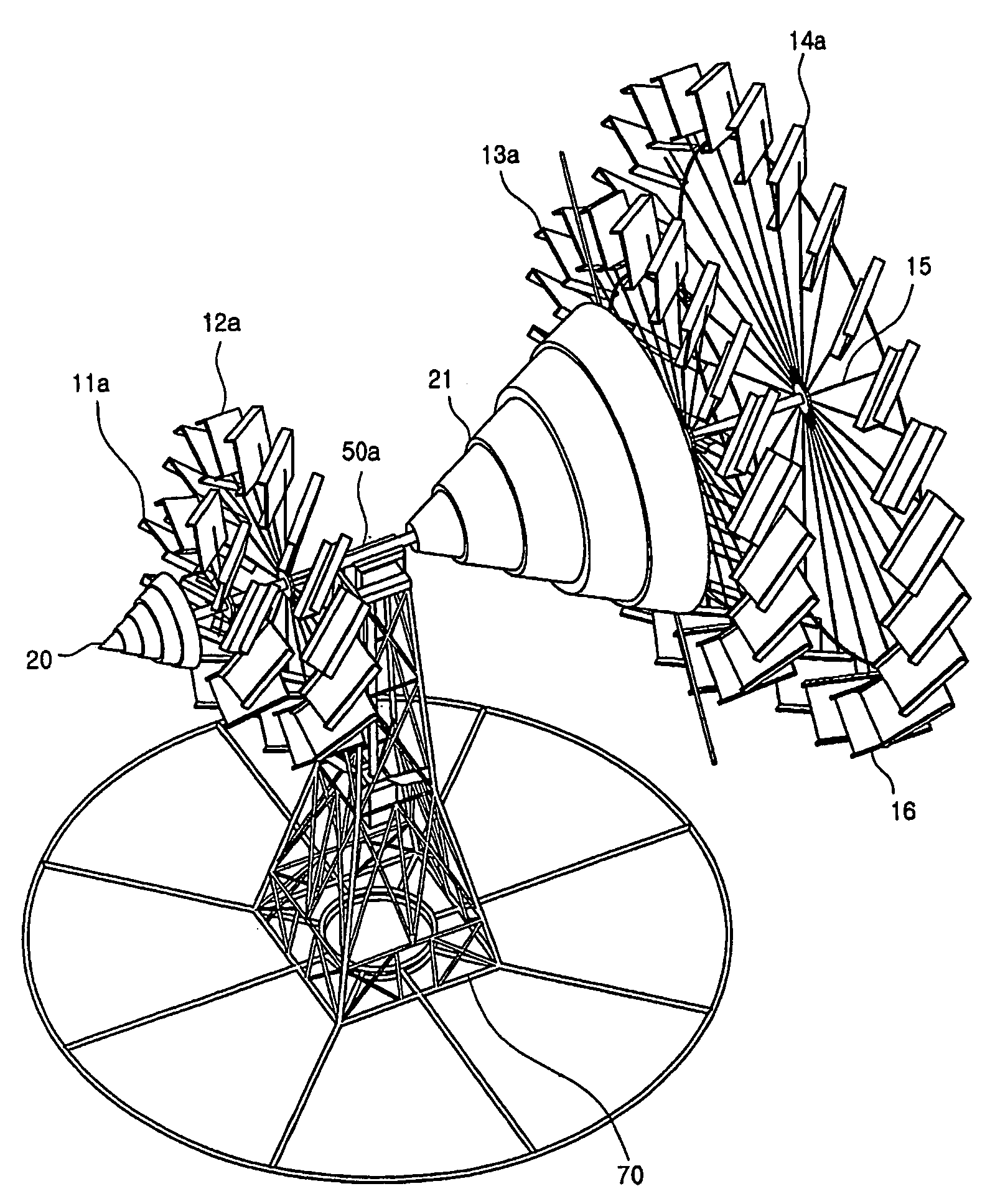
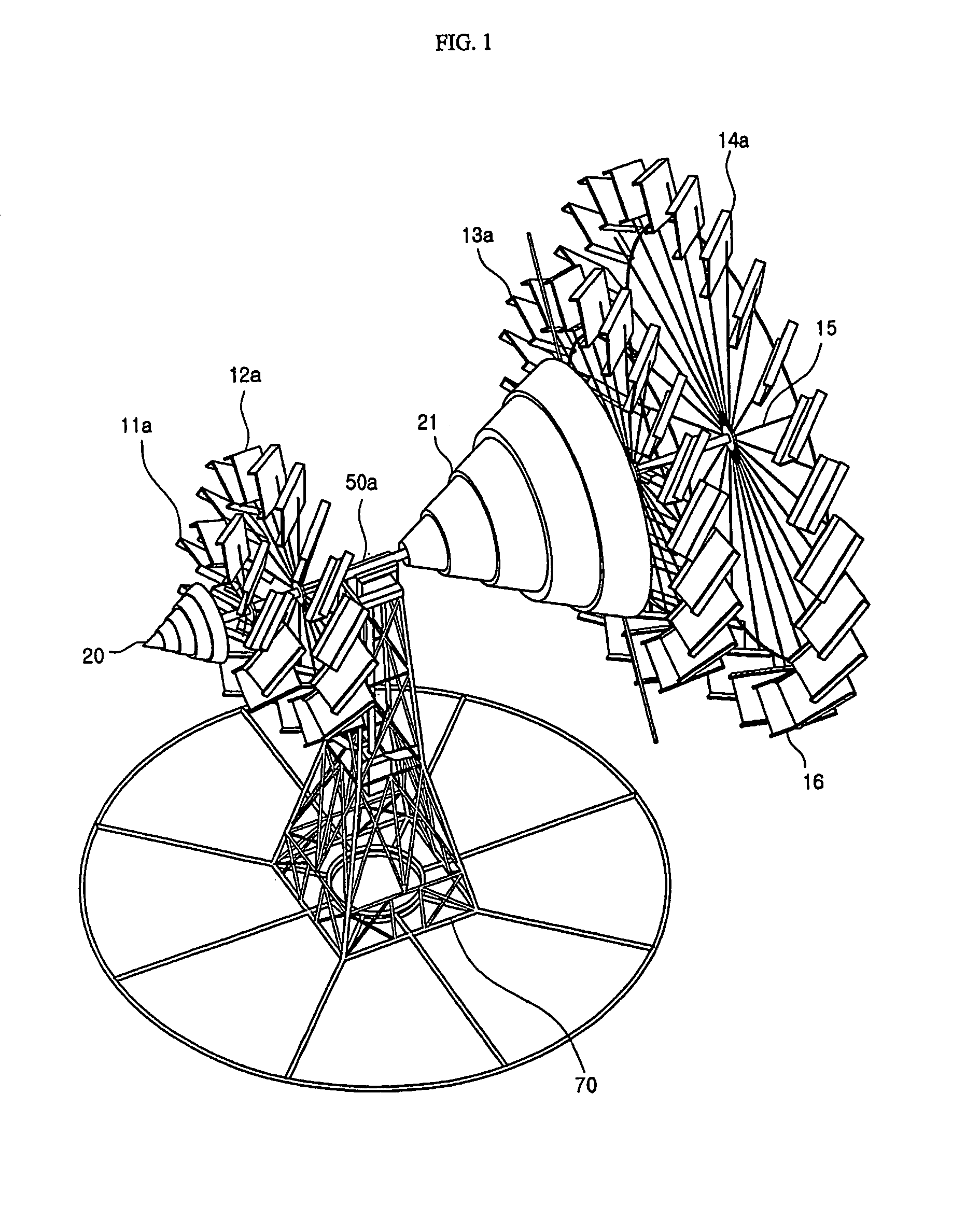
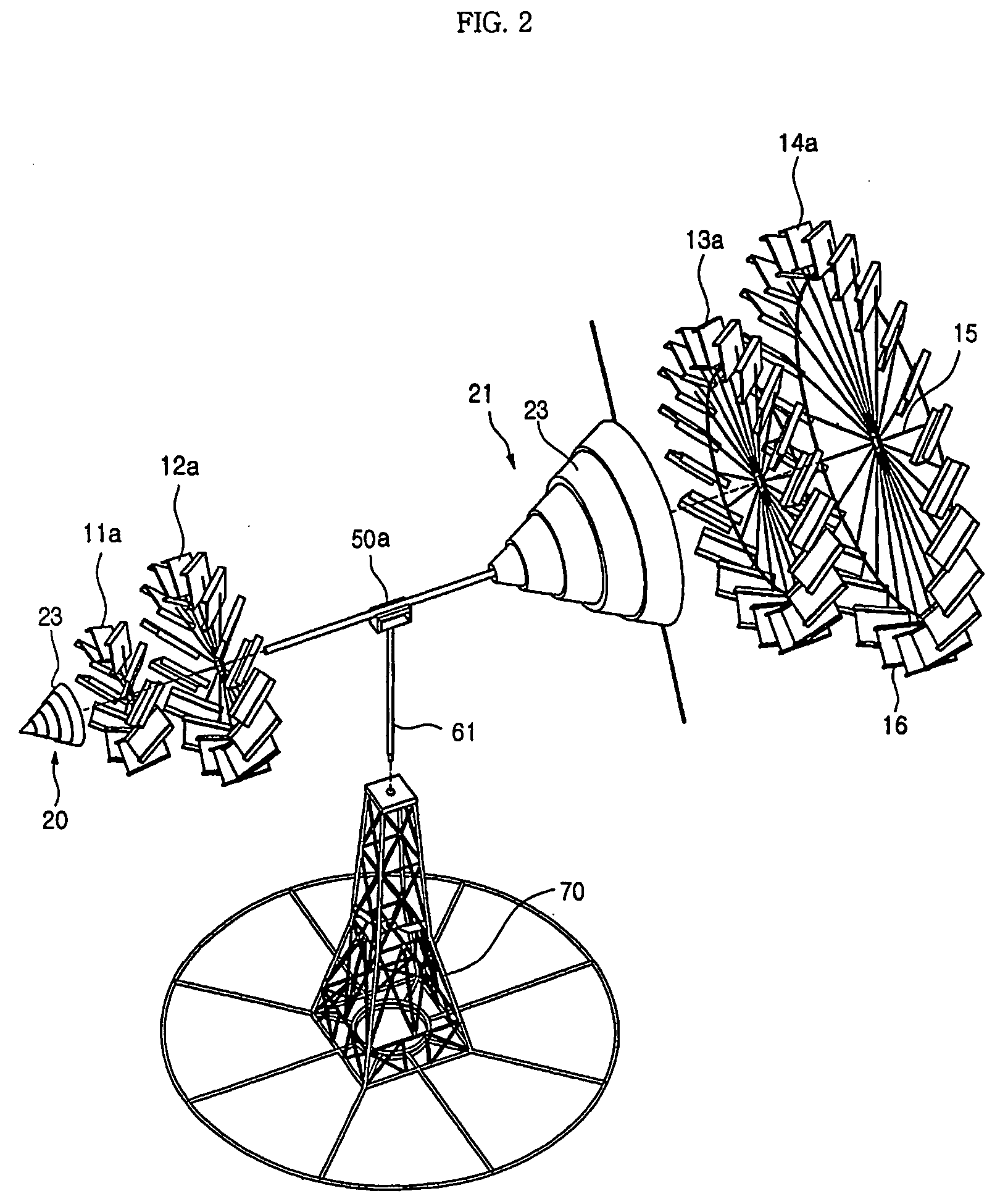
[0033]The following detailed description will present a preferred embodiment of the invention in reference to the accompanying drawings.

[0034]FIG. 1 is a perspective view of a wind power generating apparatus of the invention, FIG. 2 is an exploded perspective view of the wind power generating apparatus of the invention, FIG. 3 is a partially expanded plan view of FIG. 2, FIG. 4 is a transmission unit of the wind power generating apparatus of the invention, FIG. 5 illustrates the structure of safety means of the wind power generating apparatus of the invention, FIGS. 6A and 6B are sectional views taken along a line A—A in FIG. 5 illustrating the operation of a rotor, FIG. 7 is a partial expanded perspective view of a rotary wing of the wind power generating apparatus of the invention, FIG. 8 is a sectional view taken along a line B—B in FIG. 7, FIGS. 9A and 9B are sectional views illustrating the operation of wing supporting means of the invention, FIG. 10 is a perspective view illus...


PUM


Abstract

A wind power generating apparatus having a plurality of rotary wings can reduce the load and resistance on the rotary wings due to wind to obtain a highly effective rotation power as well as to flexibly absorb the impact applied to the rotary wings due to varying wind pressure. Each one of the rotary wings has a radius of rotation different from the others and rotates separately according to the direction of the wind, by which the rotation power resulting from load and resistance in the integrally elongated rotary wings in relation to the wind is prevented from being canceled, and the wind acceleration via the accelerator covers and the wind distribution to the rotary wings result for highly efficient rotation power. The impact on the rotary wings is elastically absorbed while supporting the rotary wings so that the rotary wings can gradually rotate according to the intensity of the wind without damage

Description

TECHNICAL FIELD[0001]The present invention relates to a wind power generating apparatus having a plurality of rotary wings. In particular, the present invention is directed to a wind power generator with multiple rotary wings in which load and resistance on the wind generated in the rotary wing are reduced to obtain a high efficiency rotation power and flexibly absorb impact applied to the rotary wing according to variation of wind pressure.BACKGROUND ART[0002]In general, electric power generations can be classified into hydroelectric power generation using head drop of water, thermal power generation which obtains electric power by means of combustion of fuel, nuclear power generation using nuclear fission and wind power generation using wind. A proper power generator is established considering season and geographic influence to obtain electric power.[0003]Among these power generations, wind power generation produces electric power utilizing natural wind and has advantages in that ...

Claims


Application Information

Patent Timeline
Patent Type & Authority Patents(United States)
IPC IPC(8): F03D1/02F03D1/04F03D1/06F03D7/04F03D9/00F03D11/02F03D11/04
CPCF03D1/02F03D1/0608Y02E10/725Y02E10/721F03D1/025F03D1/04F03D9/25Y02E10/72Y02E10/74
Inventor JOO, JANG-SIK
Owner JOO JANG SIK
Learn More