Method of installing a dental implant

a dental implant and implant technology, applied in the field of dental implants, can solve the problems of the overall complexity and the expense of the computer-driven milling machine, and achieve the effect of a better method of installing the dental implan

Inactive Publication Date: 2006-05-16
MALIN LEO J
View PDF19 Cites 111 Cited by
  • Summary
  • Abstract
  • Description
  • Claims
  • Application Information

AI Technical Summary

Benefits of technology

[0009]To provide a better method of installing a dental implant, it is an object of some embodiments of the invention to take a t

Problems solved by technology

Drawbacks of such a method include its overall complexit

Method used


Image

  • Method of installing a dental implant
  • Method of installing a dental implant
  • Method of installing a dental implant

Examples


Embodiment Construction

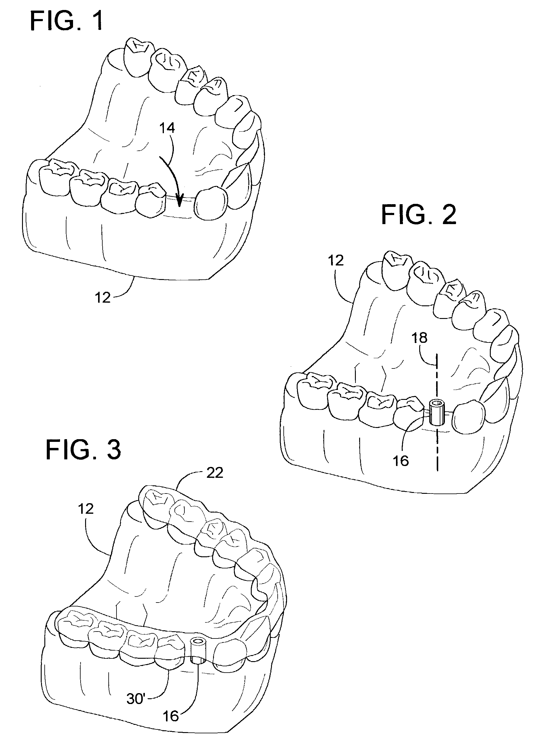
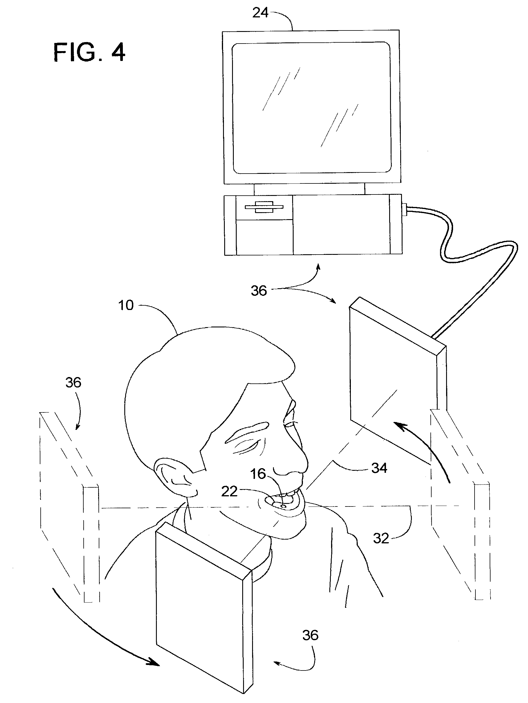
[0039]For simplicity and clarity, the invention will be described with reference to replacing a single missing tooth, however, it will be appreciated by those skilled in the art that the method can be readily applied to multiple teeth or even an entire set of teeth. Thus, the term, “crown” broadly encompasses an individual prosthetic tooth, bridge, denture, etc. For the illustrated example, a patient 10 is missing his lower-right cuspid as shown in FIGS. 1–4.

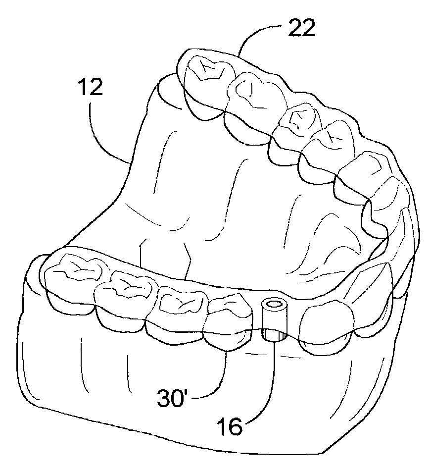
[0040]To replace the missing tooth, the process may begin by creating a cast model 12 (FIG. 1) of the patient's lower jaw. Arrow 14 indicates the general area of the missing tooth. Model 12 may be a plaster casting; however, the actual structure and method of making such a model may vary. Such models and methods of making them are well known to those skilled in the art.

[0041]In FIG. 2, a drill guide tube 16, can be placed on model 12 in the area of the missing tooth. Tube 16 is preferably made of metal or some other generally ra...


PUM


Abstract

A method of installing a dental implant includes positioning a drill guide tube adjacent to a jawbone and taking a tomographical scan of the two. Based on the scan, a computer-generated image is created and analyzed to confirm whether the drill guide tube is properly aligned. If the drill guide tube is in the correct position, that same tube to used to guide a drill bit into the jawbone. In some cases, the tube also helps guide a biopsy punch in cutting just a small, round opening into the gum tissue, which minimizes the time needed for healing.

Description

BACKGROUND OF THE INVENTION[0001]1. Field of the Invention[0002]The subject invention generally pertains to dental implants and more specifically to a method of installing them.[0003]2. Description of Related Art[0004]Various dental implant methods and devices have been developed for replacing one or more missing teeth in a person's jaw with prosthetic teeth. For many prosthetic teeth, a final product comprises three basic components: an implant, an abutment, and a crown. The crown is the exposed portion of the prosthesis that resembles one or more teeth. The implant is an anchor that becomes attached to the jawbone, and the abutment couples the crown to the implant.[0005]Typical implant methods involve a series of procedures extending over several months. In some cases, for instance, the process involves first, cutting the gum tissue in the area of the missing tooth and pulling the tissue back to expose the jawbone; second, drilling a hole into the bone; third, installing an anchor...

Claims


Application Information

Patent Timeline
IPC IPC(8): A61C3/00A61C1/08A61C8/00A61C9/00
CPCA61C1/084A61C9/004A61C8/0089A61C9/0046
Inventor MALIN, LEO J.
Owner MALIN LEO J
Why Eureka
Try Eureka