Gas sensor element

a sensor element and quick activation technology, applied in the direction of liquid/fluent solid measurement, instruments, electrochemical variables, etc., can solve the problems of difficult to effectively operate the three-way catalyst, difficult to determine the air-fuel ratio, and difficulty in determining the air-fuel ratio immediately after engine startup, so as to improve the conductivity of oxygen ions, reduce the activation temperature, and improve the effect of oxygen ions

Inactive Publication Date: 2006-05-16
DENSO CORP
View PDF15 Cites 12 Cited by
  • Summary
  • Abstract
  • Description
  • Claims
  • Application Information

AI Technical Summary

Benefits of technology

[0015]Within the limiting current range, an oxygen ion current produced by ionization of O2 on the surface of the electrode is balanced with the current produced by application of the voltage to the electrochemical cell. When the voltage applied to the electrochemical cell increases and falls within the range C, it will cause the zirconia of the solid electrolyte body to be reduced, thereby resulting in a change in crystalline structure of the solid electrolyte body. This change serves to improve the conductivity of the oxygen ions, thereby resulting in a decrease in activation temperature at which the electrochemical cell is activated.
[0016]The decrease in activation temperature is also achieved by applying the dc current to the electrochemical cell to remove the oxygen ions joined to the electrodes, thereby enhancing the activation of the electrodes.
[0017]Use of the dc current in the aging treatment facilitates activation of the electrochemical cell and the electrodes as compared with the ac current. The ac current varies in direction of flow thereof. It is, thus, difficult to have the current to flow within the above described voltage range.
[0018]The aging treatment is achieved by connecting one of the electrodes to a positive terminal and the other to a negative terminal of a dc power supply. The same effect is provided, as indicated by D and E in FIG. 7, regardless of a direction of flow of the dc current. Note that the current within the range E is the limiting current depending upon a diffusion resistance of an air chamber (i.e., the air chamber 120 as illustrated in, for example, FIGS. 2 and 3).
[0019]However, in order to decrease the activation temperature of the electrochemical cell greatly, it is preferable to apply the voltage V across the electrodes so that oxygen ions flow from one of the electrodes exposed to a gas to be measured by the gas sensor element to the other electrode exposed to a reference gas. The aging treatment causes oxygen to be ionized, so that the oxygen ion current flows from the electrode exposed to the measurement gas to the other electrode. The oxygen ions are, thus, removed from the electrode exposed to the measurement gas, thereby increasing the activation of the electrode greatly.
[0020]When the concentration of oxygen is measured by the gas sensor element, the ionization of oxygen is taken placed on the electrode exposed to the measurement gas. Increasing the activation of the electrode will result in a decrease in activation temperature thereof, thereby facilitating the activation of the gas sensor element.

Problems solved by technology

Usually, it is impossible to determine the air-fuel ratio until the temperature of the gas sensor element reaches an activation temperature thereof.
It is, therefore, difficult to perform the air-fuel ratio control immediately after startup of the engine.
Specifically, conventional air-fuel ratio control systems have difficulty in controlling the air-fuel ratio correctly until the temperature of the gas sensor element reaches the activation temperature thereof after startup of the engine, which may result in a difficulty in operating the three-way catalyst effectively, so that exhaust gasses containing a high concentration of pollutant are discharged directly to the air.
This results in an increase in electrical resistance of the gas sensor element, thus causing the activation temperature of the gas sensor element to be increased undesirably, which leads to a difficulty in activating the gas sensor element quickly immediately after startup of the engine.

Method used


Image

  • Gas sensor element
  • Gas sensor element
  • Gas sensor element

Examples


first embodiment

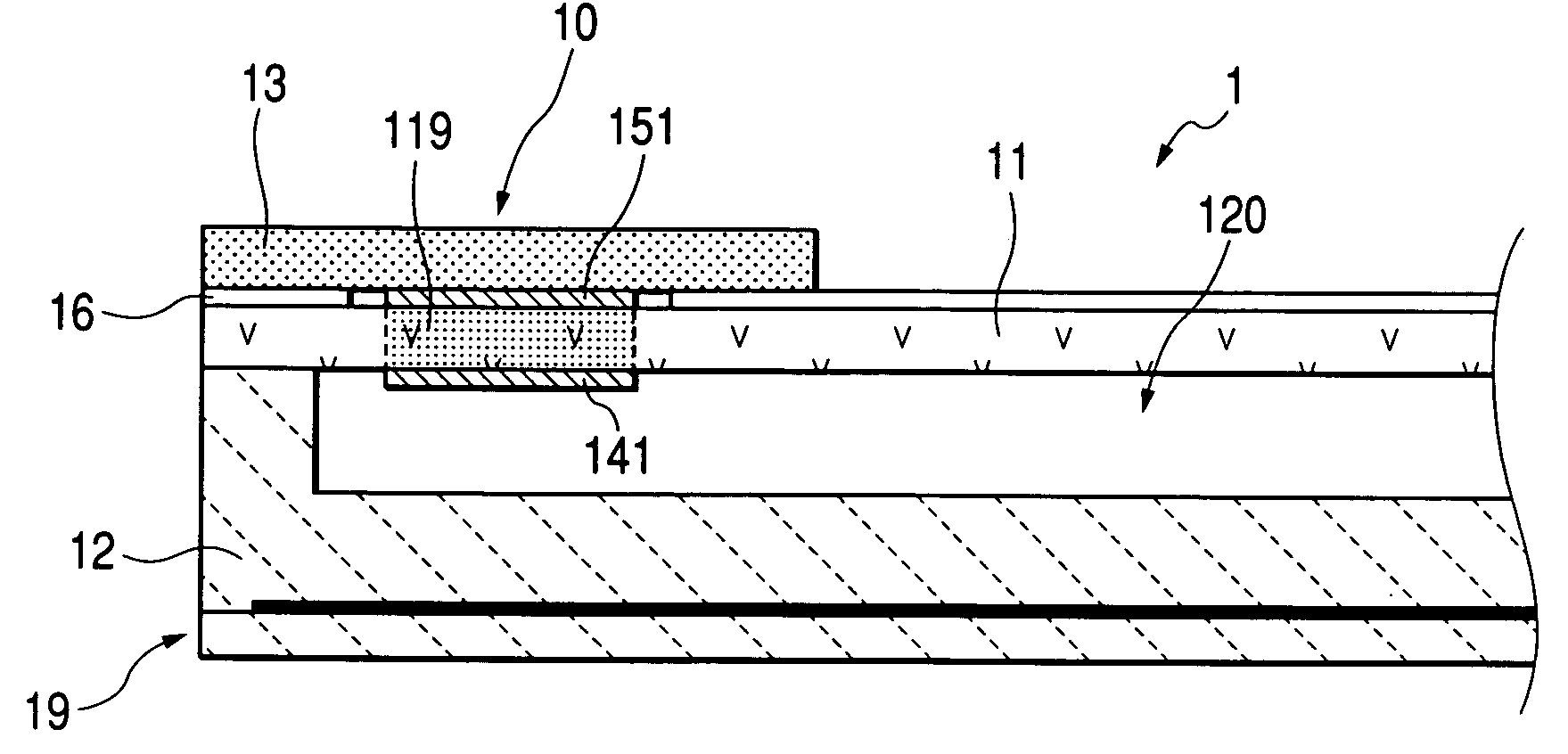
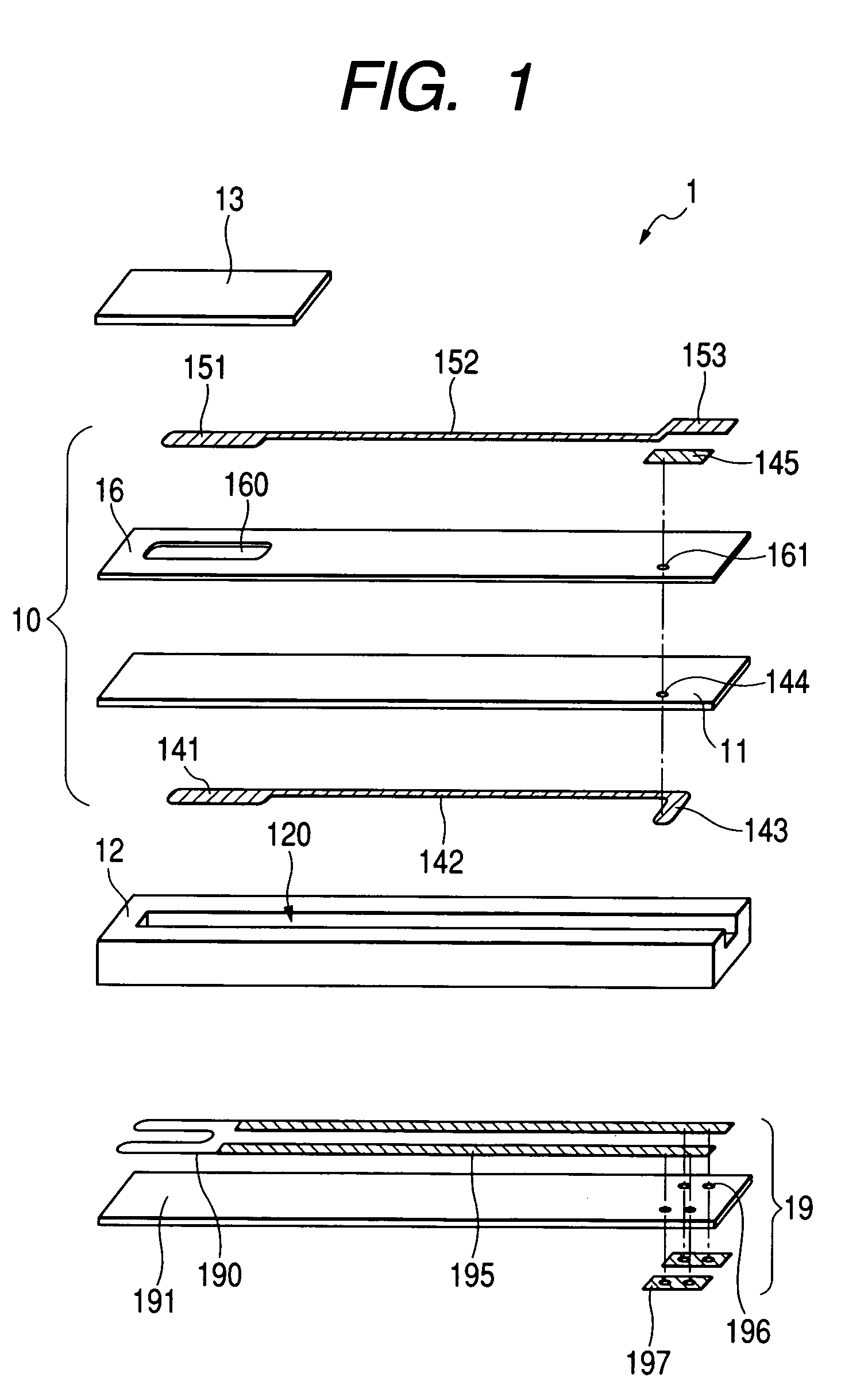
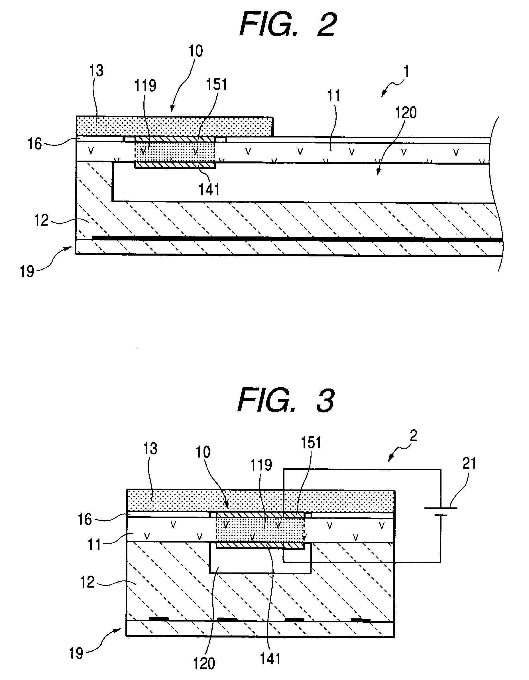
[0053]Referring now to the drawings, wherein like numbers refer to like parts in several views, particularly to FIGS. 1, 2 and 3, there is shown a gas sensor element 1 according to the invention which may be incorporated within a gas sensor installed in an exhaust pipe of an automotive engine to measure the concentration of oxygen (O2) or an unburned component contained in exhaust gasses of the engine in order to determine an air-fuel ratio of a mixture supplied to combustion chambers of the engine for use in air-fuel ratio control. An overall structure of such a gas sensor is not essential, and explanation thereof in detail will be omitted here. For example, U.S. Pat. No. 5,573,650, issued Nov. 12, 1996 to Fukaya et al., teaches an oxygen sensor equipped with a laminated sensor element, disclosure of which is incorporated herein by reference.

[0054]The gas sensor element 1 is of a single cell structure which is equipped with an electrochemical cell 10 consisting of a solid electroly...

fifth embodiment

[0084]The present invention is not limited to the A / F sensor and may alternatively be used with a variety of gas sensors such as NOx, HC, and CO sensors (see the fifth embodiment as discussed later).

[0085]While the aging treatment is, as described above, performed using the voltage V between V2 and 2V2, the voltage V lies preferably within a range of 1.2V2 to 1.5V2.

[0086]The aging treatment is preferably performed while the temperature of the gas sensor element 1 is kept at 500° C. to 1000° C. using, for example, the heater 19.

[0087]When the temperature is less than 500° C., it results in a great variation in V2 between individual gas sensor elements, thereby making it difficult to apply the dc current to the electrochemical cell 10 of all the gas sensor elements at the voltage V of V2 to 2V2.

[0088]When the temperature is more than 1000° C., it results in a great variation in degree of the current flowing through the electrochemical cell 10 upon application of the voltage V, which l...

fourth embodiment

[0101]The fourth embodiment will be described below in which the aging treatment is performed on an electromotive force gas sensor element 3 as illustrated in FIG. 11.

[0102]The gas sensor element 3 is made of a laminate of the porous protective layer 31, the solid electrolyte plate 11, the spacer 12, and the ceramic heater 19.

[0103]The solid electrolyte plate 11 has the electrodes 141 and 151. The electrode 141 is, like the first embodiment, exposed to the air chamber 120 and works as a reference gas electrode. The electrode 151 is covered with the porous protective layer 31 and exposed to a gas to be measured.

[0104]The gas sensor element 3 is designed to produce a potential difference between the electrodes 141 and 151 as a function of a difference in oxygen concentration of the reference gas and the measurement gas. The concentration of oxygen (O2) to which the electrode 151 is exposed is determined as a function of the potential difference.

[0105]The porous protective layer 31 has...


PUM

PropertyMeasurementUnit
temperatureaaaaaaaaaa

Abstract

A gas sensor element which may be employed in measuring the concentration of gas such O2, NOx, or CO. The gas sensor element consists of an electrochemical cell made up of a solid electrolyte body formed by a partially stabilized zirconia and a pair of electrodes disposed on the solid electrolyte body. The electrochemical cell is subjected to an aging treatment in which the dc current is applied to the electrodes at a given voltage to enhance the activation of the electrochemical cell.

Description

BACKGROUND OF THE INVENTION[0001]1. Technical Field of the Invention[0002]The present invention relates generally to a quickly activatable structure of a gas sensor element which may be built in a gas sensor employed in an air-fuel ratio control system for automotive vehicles for measuring the concentration of gas such O2, NOx, or CO, and a production and a reconditioning method thereof.[0003]2. Background Art[0004]In order to operate a three-way catalyst effectively for converting air pollutants contained in exhaust emissions of automotive engines into harmless products, it is essential to control burning of the engine so as to keep an air-fuel ratio of a mixture within a combustion chamber of the engine within a limited range.[0005]Such air-fuel ratio control typically employs a gas sensor designed to measure the concentration of oxygen (O2) or an unburned gas contained in exhaust emissions of the engine. A gas sensor of such a type is equipped with a gas sensor element having an ...

Claims


Application Information

Patent Timeline
Patent Type & Authority Patents(United States)
IPC IPC(8): G01N27/41G01N27/407G01N33/00
CPCG01N27/4074
Inventor NAKAE, MAKOTONAITO, SUSUMUFUJII, NAMITSUGUSANO, HIROMISUGIYAMA, TOMIONAKAGAWA, KAZUYA
Owner DENSO CORP
Why Eureka
Try Eureka