Electric arc welding device, method of welding metal sheets to metallic counterpieces, and welding element

a technology of electric arc welding and counterpieces, which is applied in the direction of arc welding apparatus, welding apparatus, manufacturing tools, etc., can solve the problem of requiring a relative large mass of sheet metal for fastening elements, and achieve the effect of reducing energy consumption in welding operation, increasing arc voltage, and reducing welding costs

Inactive Publication Date: 2006-05-16
NEWFREY
View PDF8 Cites 11 Cited by
  • Summary
  • Abstract
  • Description
  • Claims
  • Application Information

AI Technical Summary

Benefits of technology

[0018]The arc set up by the electric arc welding device according to the invention may possess a lower energy than in the known WELDFAST system. Hence, welding operations generally can be carried out with lower energy outlay. Also, it is possible to weld the sheets onto counterpieces in the form of thinner plates, since there is less danger of burning these plates through in the neighborhood of the welded seam.
[0034]Also, it is of especial advantage over all if the sheet metal and / or counterpiece surfaces to be welded are cleaned by means of an electric arc moved along these surfaces by means of the magnetic field, carrying a current whose magnitude is smaller than that of a welding current. The electric arc cleaning current is so chosen that the face of the sheet metal and the counterpiece are not yet incipiently fused, but rather the joining zone is cleared of surface coatings and soilage. In this way, at small welding current, extremely low-sputter welds can be produced.

Problems solved by technology

A disadvantage here is that a relatively large mass of the sheet metal of the fastening element is required for the welding segment to be laid parallel on the body sheet-metal.

Method used


Image

  • Electric arc welding device, method of welding metal sheets to metallic counterpieces, and welding element
  • Electric arc welding device, method of welding metal sheets to metallic counterpieces, and welding element
  • Electric arc welding device, method of welding metal sheets to metallic counterpieces, and welding element

Examples


Embodiment Construction

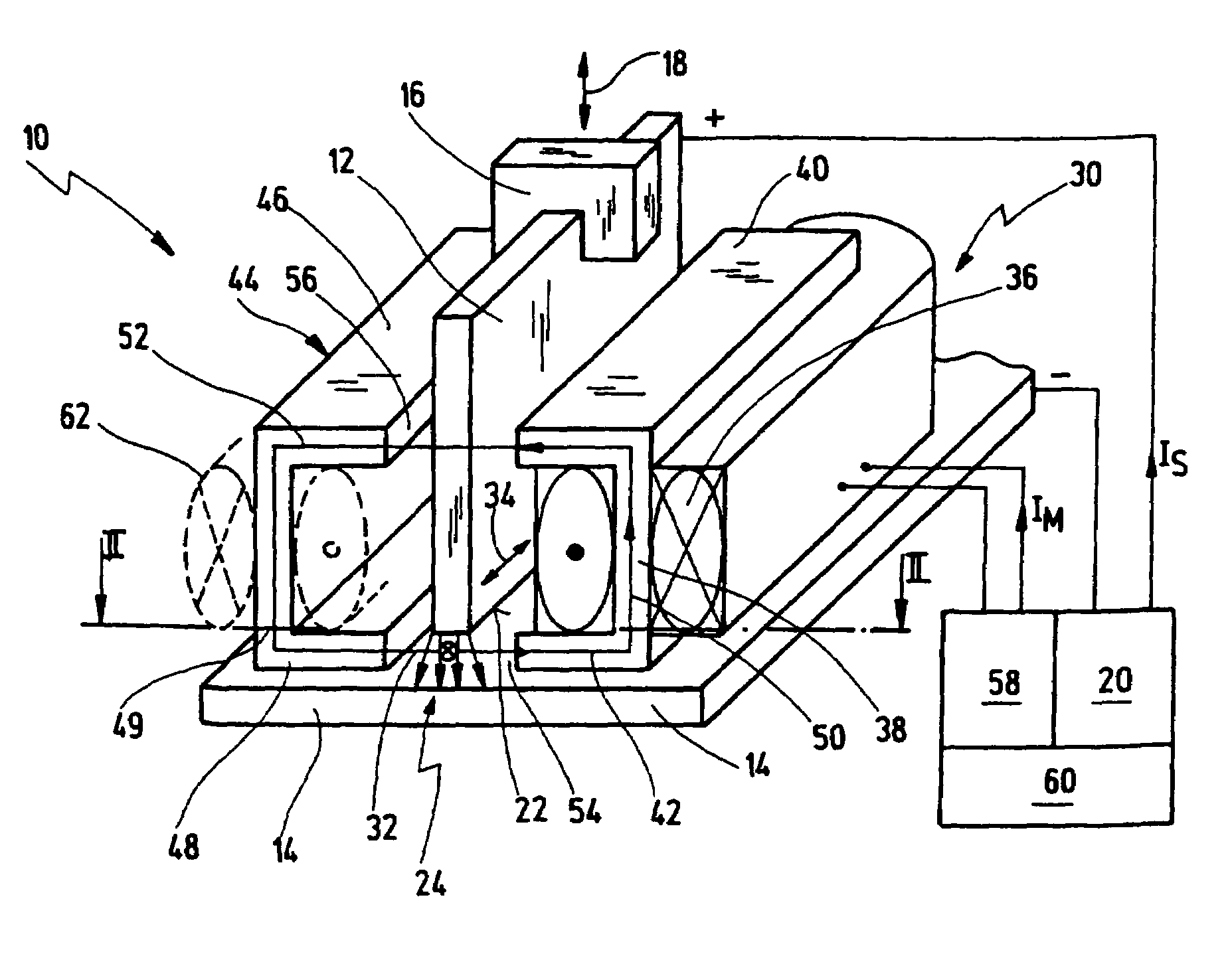
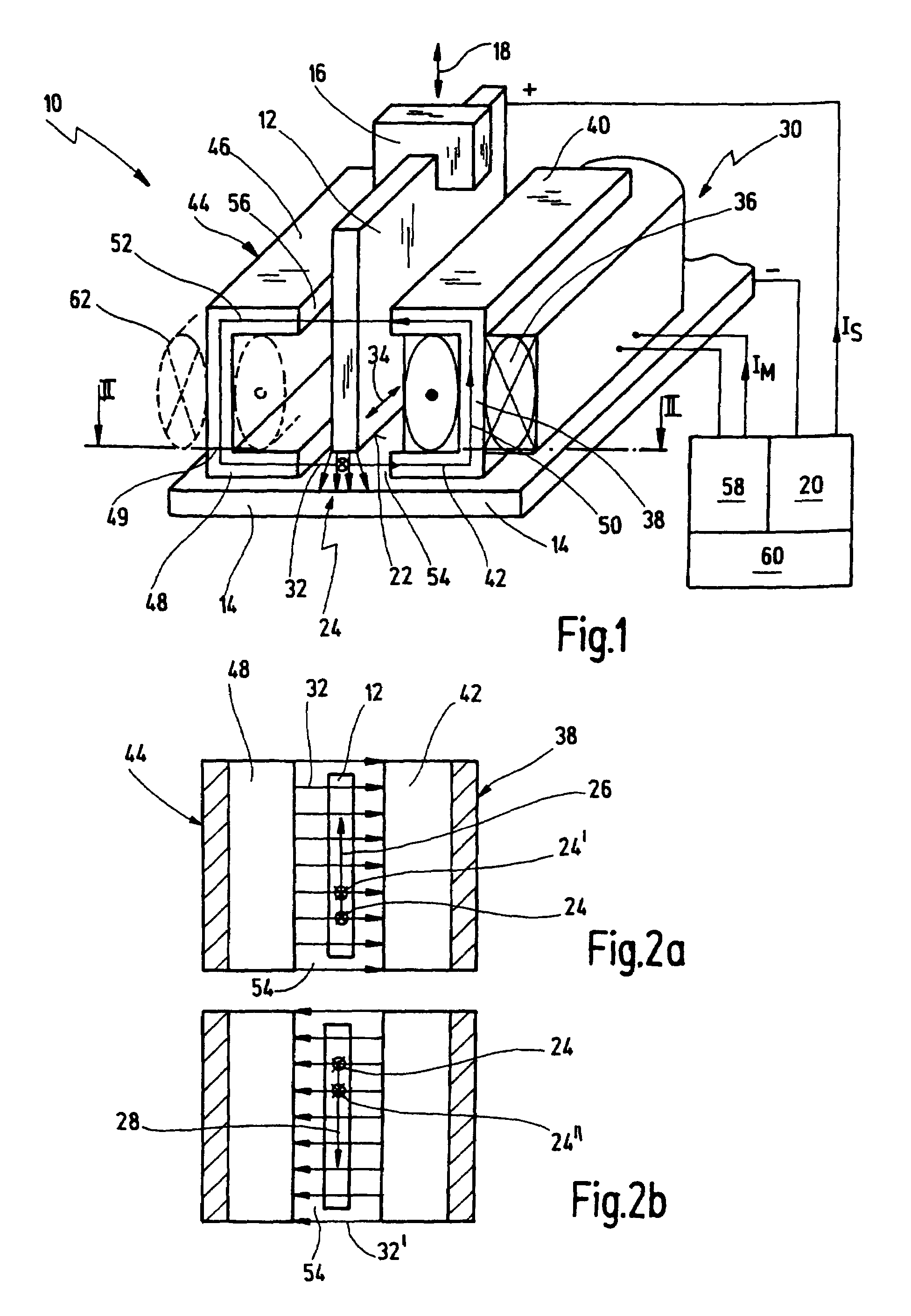
[0051]In FIGS. 1 and 2, a first embodiment of an electric arc welding device according to the invention is generally designated 10. The electric arc welding device (hereinafter, the welding device) serves to butt weld a welding element in the form of an elongated sheet or sheet segment 12 of metal onto a counterpiece in the form of a countersheet 14, for example a body sheet of a motor vehicle.

[0052]The welding device 10 comprises a holding device 16 to hold the sheet 12. A schematically indicated reciprocating device 18 serves to move the holding device 16 with sheet 12 to and fro, namely towards the counterpiece 14 and away from the counterpiece 14. A voltage supply device 20 serves to apply an electric voltage from sheet 12 to counterpiece 14.

[0053]The welding device 10 shown operates by the so-called reciprocating ignition process. That is, a face 22 of sheet 12, facing the counterpiece 14, is lowered to butt against the counterpiece 14, generally arranged transverse or perpendi...


PUM

PropertyMeasurementUnit
welding currentaaaaaaaaaa

Abstract

An electric arc welding device (10) for butt welding metallic sheets (12; 72; 80; 90; 92; 94; 100) is provided having an elongated face (22) onto metallic counterpieces (14), having a holding device (16; 16, 74) for holding a sheet (12, 72; 80; 90; 92; 94; 100), a reciprocating device (18) for moving the holding device (16; 16, 74) to and fro towards the counterpiece (14) and away from it, and a voltage supply device (20) for applying a voltage between sheet (12; 72; 80; 90; 92; 94; 100) and counterpiece (14) in order to generate an electric arc (24) between them. A magnetic field generating device (30) is provided, designed to generate a magnetic field (50, 32) having a component (32) transverse to the extent of the elongated face (22) and transverse to the extent of the electric arc (24) generated in the welding operation, in order to move the electric arc (24) in the direction of the extent of the elongated face (22).

Description

CROSS-REFERENCE TO RELATED APPLICATIONS[0001]This application claims the benefit of German Patent Application DE 102 53 415.2, filed Nov. 8, 2002. The disclosure of the above application is incorporated herein by reference.FIELD OF THE INVENTION[0002]The present invention relates to an electric arc welding device for butt welding of metallic sheets having an elongated face to metallic counterpieces, having a holding device for holding a sheet, a reciprocating device for moving the holding device to and fro towards and away from the counterpiece, and a voltage supply device for applying a voltage between sheet and counterpiece, in order to produce an electric arc between them.[0003]Further, the present invention relates to a method of butt welding metallic sheets having an elongated face to metallic counterpieces, a voltage being applied between the sheet and the counterpiece, an electric arc being set up between the sheet and the counterpiece by means of which the face of the sheet ...

Claims


Application Information

Patent Timeline
Patent Type & Authority Patents(United States)
IPC IPC(8): B23K9/08B23K9/20
CPCB23K9/08
Inventor SCHMITT, KLAUS GISBERT
Owner NEWFREY
Why Eureka
Try Eureka