Illuminating apparatus using full-color LEDs

a technology of led lights and illumination apparatuses, applied in lighting and heating apparatuses, instruments, process and machine control, etc., can solve the problems of current value and differences in light intensity of led lights, and achieve the effect of constant voltage drop for each emission color, setting the most accurately and properly

Inactive Publication Date: 2006-05-16
TOKI
View PDF5 Cites 10 Cited by
  • Summary
  • Abstract
  • Description
  • Claims
  • Application Information

AI Technical Summary

Benefits of technology

[0011]According to this embodiment, the voltage drop for each emission color becomes constant by providing and connecting a current regulation diode with a light emitting element. By employing the current regulation diode, the voltage drop and the current value can be set most accurately and properly, thus enabling the color tone of emission color for each light-emitting unit to be uniform.

Problems solved by technology

When a large number of LEDs are connected to a cable dozens of meters long, a difference results in current value between the ends of the cable due to a voltage drop, and hence there will be differences in light intensity of the LEDs.

Method used


Image

  • Illuminating apparatus using full-color LEDs
  • Illuminating apparatus using full-color LEDs
  • Illuminating apparatus using full-color LEDs

Examples


first embodiment

[0019]An illuminating apparatus according to a first embodiment is, for instance, what is called “tape light”, an outdoor or indoor decorative illumination used in commercial spaces.

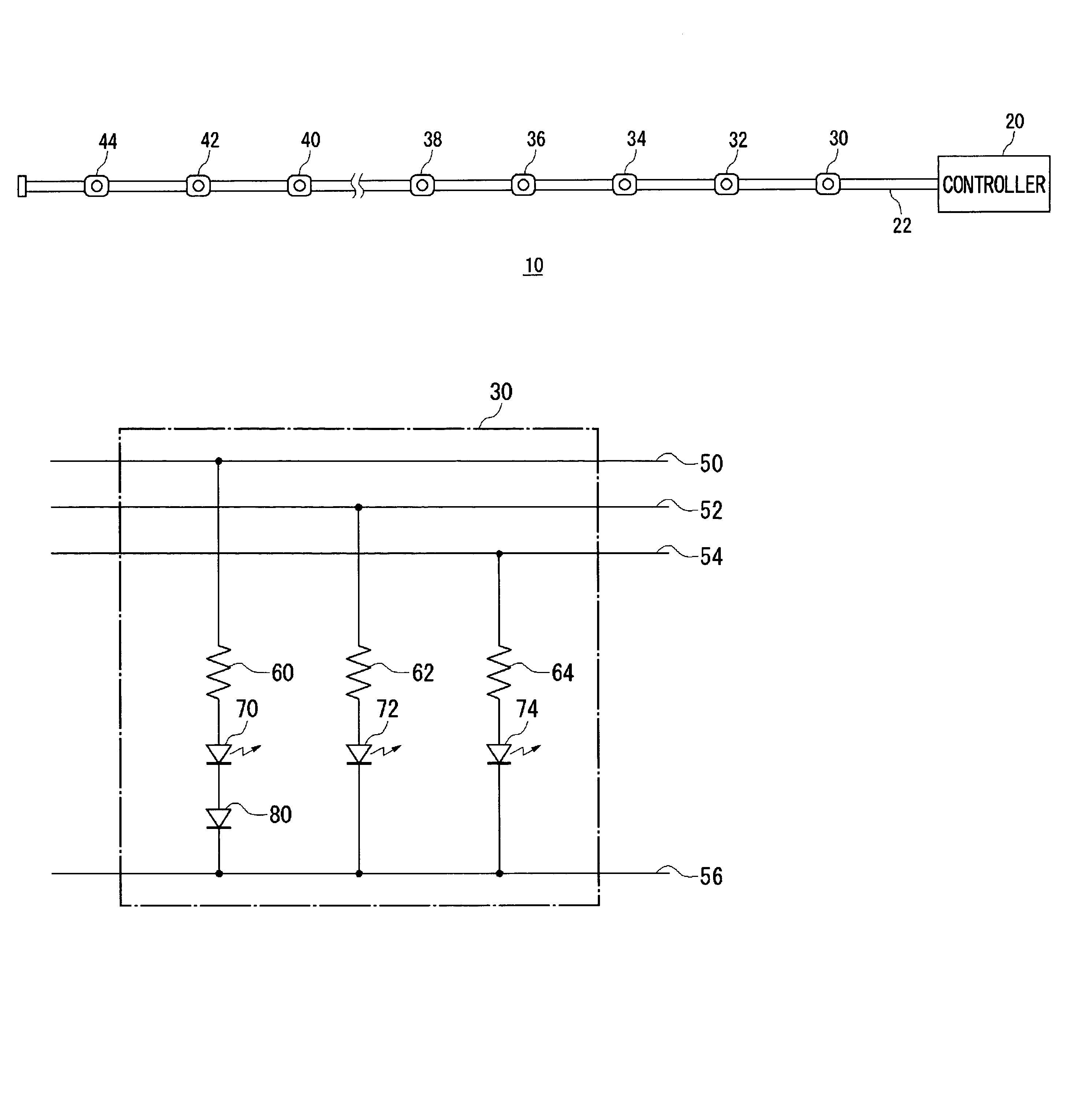
[0020]FIG. 1 shows a general structure of an illuminating apparatus. The illuminating apparatus 10 is comprised of a controller 20, a power supply cable 22 and a plurality of light-emitting units. The plurality of light-emitting units shown in FIG. 1 are a first light-emitting unit 30, a second light-emitting unit 32, a third light-emitting unit 34, a fourth light-emitting unit 36, a fifth light-emitting unit 38, a sixth light-emitting unit 40, a seventh light-emitting unit 42 and an eighth light-emitting unit 44.

[0021]The power supply cable 22 is, for example, a cable about 20 meters long, formed in a flat tape-like structure containing four conductors disposed in parallel with one another with a resin member covering them. The light-emitting units are connected to the power supply cable 22 and provided...

second embodiment

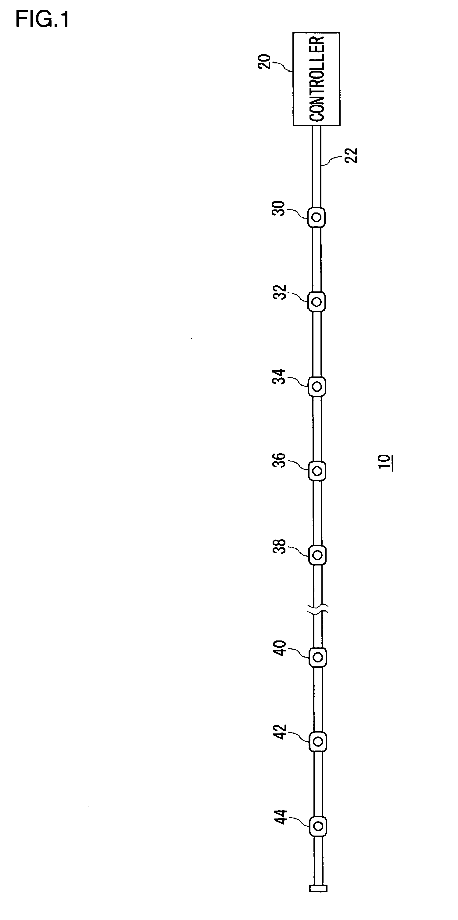
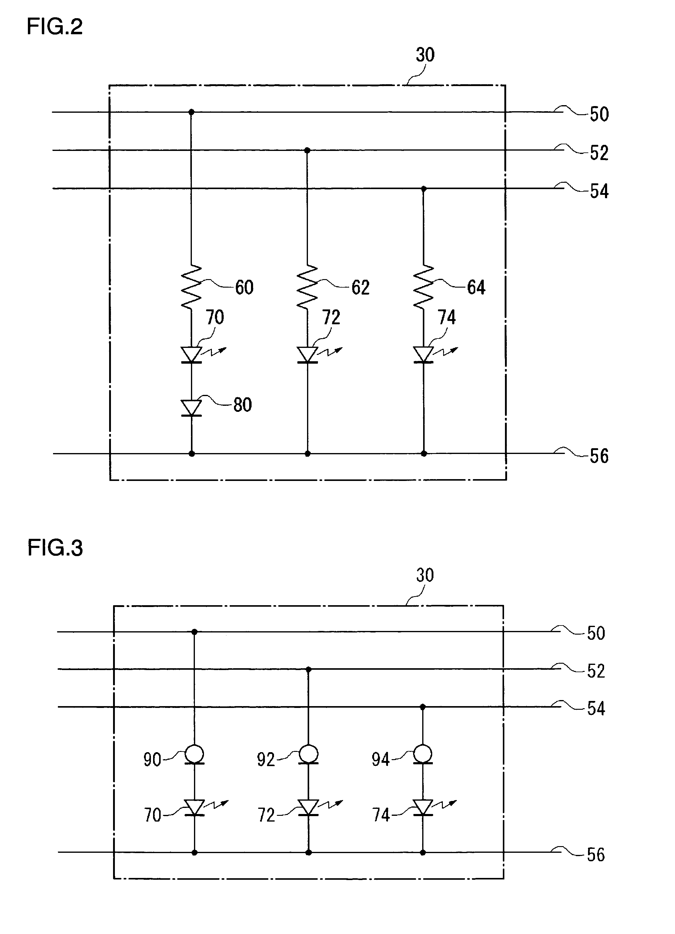
[0031]FIG. 3 shows an electrical structure of a first light-emitting unit 30 according to a second embodiment. An illuminating apparatus of this second embodiment differs from the first embodiment in that the difference in the tone of emission colors is eliminated by using current regulation diodes. That is, current regulation diodes 90, 92 and 94 are provided in place of the red resistance 60, the green resistance 62 and the blue resistance 64, respectively, and they are set such that the currents flowing to the red LED 70, the green LED 72 and the blue LED 74 become equal. In this manner, current regulation diodes can also make the current for the LEDs of each color constant. As a result, there will be little difference in the tone of emitted colors since variation in the effects of voltage drop for each color is reduced to almost none between the first light-emitting unit 30 and the eighth light-emitting unit 44, which are located close to the respective ends of the power supply ...

third embodiment

[0033]FIG. 4 shows an electrical structure of a first light-emitting unit 30 according to a third embodiment. An illuminating apparatus according to this third embodiment differs from the first embodiment in that the red LED 70, the green LED 72, the blue LED 74 and the auxiliary diode 80 are connected in such a direction as to have the opposite polarity. That is, the cathodes of the red LED 70, the green LED 72 and the blue LED 74 are connected to one end of the red resistance 60, the green resistance 62 and the blue resistance 64, respectively, and the anode of the red LED 70 is connected to the cathode of the auxiliary diode 80. The anodes of the green LED 72, the blue LED 74 and the auxiliary diode 80 are connected to the common line 56. This arrangement can also produce the same advantageous effect as the first embodiment.


PUM


Abstract

An illuminating apparatus according to the present invention comprises a controller, a power supply cable and a plurality of light-emitting units. The plurality of light-emitting units shown are a first light-emitting unit, a second light-emitting unit, a third light-emitting unit, a fourth light-emitting unit, a fifth light-emitting unit, a sixth light-emitting unit, a seventh light-emitting unit and an eighth light-emitting unit. Each light-emitting unit is provided with a red LED, a green LED and a blue LED. A diode is connected to the red LED whose forward voltage is lower.

Description

BACKGROUND OF THE INVENTION[0001]1. Field of the Invention[0002]The present invention relates to illuminating apparatus, and it particularly relates to a technology by which to maintain the desirable state of light generation.[0003]2. Description of the Related Art[0004]LEDs (Light Emitting Diodes) are known as relatively low-priced light-emitting elements. LEDs come in various types that emit light of red, green and various other colors, and special attention is being directed to the blue LEDs, which have been finding practical application in recent years. With three primary colors ready now, it is possible to produce full-color display apparatuses using LEDs (see, for example, Reference (1) in the following Related Art List), and a variety of other applications are expected for LEDs.RELATED ART LIST(1) Japanese Patent Application Laid-Open No. 2002-353519.[0005]Of the LEDs for three primary colors used for full-color light emissions, the red LED requires a lower forward voltage (V...

Claims


Application Information

Patent Timeline
Patent Type & Authority Patents(United States)
IPC IPC(8): G05F1/00F21S4/00H01L33/00F21S10/00G09G3/32H05B37/02
CPCH05B33/0821H05B33/0857H05B33/0827Y10S362/80H05B45/20H05B45/40H05B45/46
Inventor GOTO, HIROMITSU
Owner TOKI
Why Eureka
Try Eureka