High side NFET gate driving circuit

a driving circuit and high-side technology, applied in the direction of oscillator generators, electronic switching, pulse techniques, etc., can solve the problems of difficult to solve and expensive solutions

Inactive Publication Date: 2006-05-16
SAUER DANFOSS NORDBERG
View PDF19 Cites 21 Cited by
  • Summary
  • Abstract
  • Description
  • Claims
  • Application Information

AI Technical Summary

Problems solved by technology

This can be a difficult problem to solve as the most positive voltage in a system is commonly the supply voltage.
The two requirements of driving the gate to a voltage above the source voltage and driving the source voltage rapidly commonly lead to an expensive solution.

Method used


Image

  • High side NFET gate driving circuit
  • High side NFET gate driving circuit

Examples


Embodiment Construction

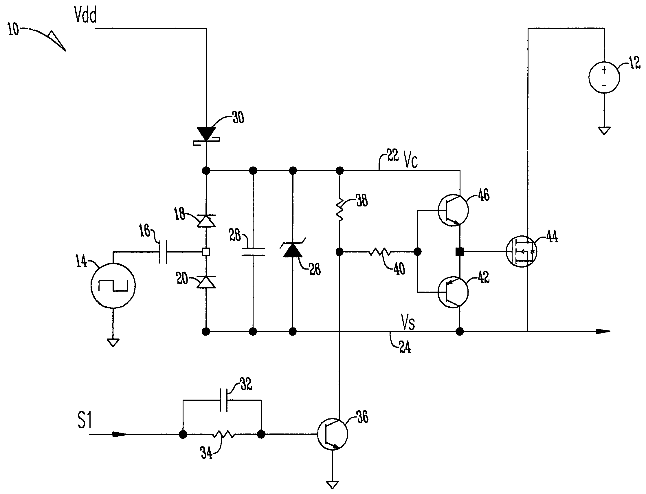
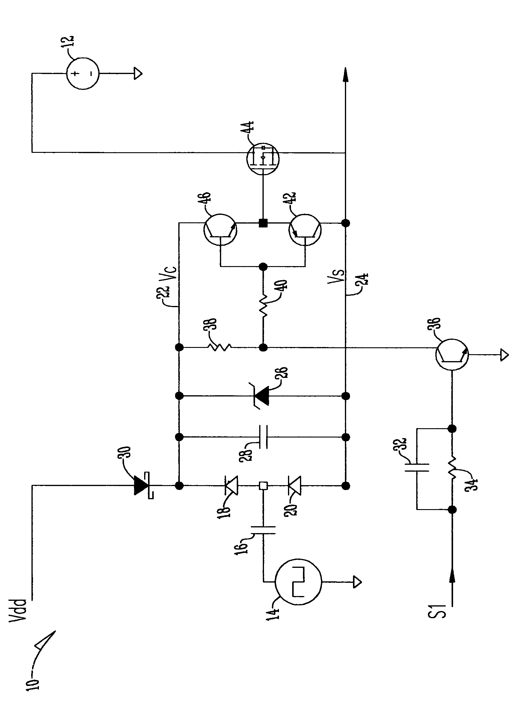
[0014]The circuit 10 of the present invention has a logic supply voltage Vdd and a battery voltage 12 supplying voltage to the system. The circuit also has an input S1 and an oscillator 14 that is used to drive the charge pump circuit that is comprised of first capacitor 16 and first and second diodes 18 and 20 respectively, thus creating a local positive voltage (Vc) along the passageway 22. The local positive voltage of passageway 22 is clamped with respect to the passageway 24 having a source voltage (Vs) by the third diode 26 that is in parallel relation with first and second diodes 18 and 20. Also, in parallel relation with both first second and third diode 18, 20, and 26 is a second capacitor 28. Additionally, the logic supply voltage (Vdd) is electrically connected to a fourth diode 30. The input S1 is received by a third capacitor 32 that is in parallel with a first resistor 34 that is electrically connected to a first transistor 36. The first transistor 34 is electrically c...


PUM


Abstract

A circuit that provides for a high side NFET gate driver that uses a circuit using only common capacitors, diodes, resistors, and transistors to create a high side NFET gate driver. The system is operated so that when there is a high input the NFET will turn off and when there is a low input the NFET will turn on.

Description

[0001]This application is a continuation of application Ser. No. 10 / 751,081 filed Jan. 2, 2004, which issued as U.S. Pat. No. 6,975,146.BACKGROUND OF THE INVENTION[0002]MOSFETs (metal oxide semi conductor field effect transistors) are widely used as electrically controlled switches. N channel MOSFETs, or NFETs, are used more often than P channel MOSFETs, or PFETs, because they have inherently lower ON resistance. NFETs lower ON resistance is because of the higher mobility of electrons vs. holes. NFETs require a positive gate voltage to allow current to flow from drain to source (“turn the NFET on” or “close the switch”).[0003]A common switch application is one that switches power to a load, or closes a connection between a positive voltage source and a load sinking current to a lower potential, typically a ground. This is commonly referred to as a “high side” switch. If an NFET is to be used as a high side switch, the gate must be charged above the positive voltage source of the NFE...

Claims


Application Information

Patent Timeline
Patent Type & Authority Patents(United States)
IPC IPC(8): H03K3/00H03K17/687H03K3/80H03K17/06
CPCH03K17/063
Inventor SCHOTTLER, JOSEPH J.
Owner SAUER DANFOSS NORDBERG
Why Eureka
Try Eureka