Dynamic phase-locked loop circuits and methods of operation thereof

a phase-locked loop and dynamic technology, applied in the direction of oscillator tubes, pulse automatic control, electrical equipment, etc., can solve the problems of jitter and jitter in single-loop pll designs that use voltage controlled oscillators (vcos), and the disadvantage of loop bandwidth versus operating frequency rang

Active Publication Date: 2006-05-16
INTEGRATED DEVICE TECH INC
View PDF16 Cites 42 Cited by
  • Summary
  • Abstract
  • Description
  • Claims
  • Application Information

AI Technical Summary

Benefits of technology

[0007]In additional embodiments of the present invention, the charge pump circuit includes a first charge pump circuit, and the transfer function control circuit further includes a second charge pump circuit that controls the oscillator control voltage when the first charge pump circuit is disabled. The transfer function control circuit may be operative to disable the first charge pump based on a first voltage range criterion for the oscillator control voltage, to cause the second charge pump circuit to drive the oscillator control voltage to a voltage indicative of reduced phase / frequency error while the first charge pump is disabled, and to re-enable the first charge pump based on a second voltage range criterion for the oscillator control voltage. In still further embodiments of the present invention, the transfer function control circuit includes a window comparator circuit operative to generate a limit signal indicative of a relationship between the oscillator control voltage and a voltage window, and a transfer function selector circuit that causes the controlled oscillator to operate according to a selected transfer function responsive to the limit signal.

Problems solved by technology

A common issue in designing PLLs is achieving a PLL with both wide frequency range and desirable jitter suppression.
For example, some conventional single-loop PLL designs that use voltage controlled oscillators (VCOs) may suffer from a disadvantageous tradeoff of loop bandwidth versus operating frequency range.
In particular, as gain of the VCO is increased to increase the frequency range of the PLL, there may be a concomitant increase in susceptibility to jitter.
Such an approach may be disadvantageous in some applications in which it is desirable to provide dynamic operation of over a wide range of frequencies.

Method used


Image

  • Dynamic phase-locked loop circuits and methods of operation thereof
  • Dynamic phase-locked loop circuits and methods of operation thereof
  • Dynamic phase-locked loop circuits and methods of operation thereof

Examples


Embodiment Construction

[0015]Specific exemplary embodiments of the invention now will be described with reference to the accompanying drawings. This invention may, however, be embodied in many different forms and should not be construed as limited to the embodiments set forth herein; rather, these embodiments are provided so that this disclosure will be thorough and complete, and will fully convey the scope of the invention to those skilled in the art. In the drawings, like numbers refer to like elements. It will be understood that when an element is referred to as being “connected” or “coupled” to another element, it can be directly connected or coupled to the other element or intervening elements may be present.

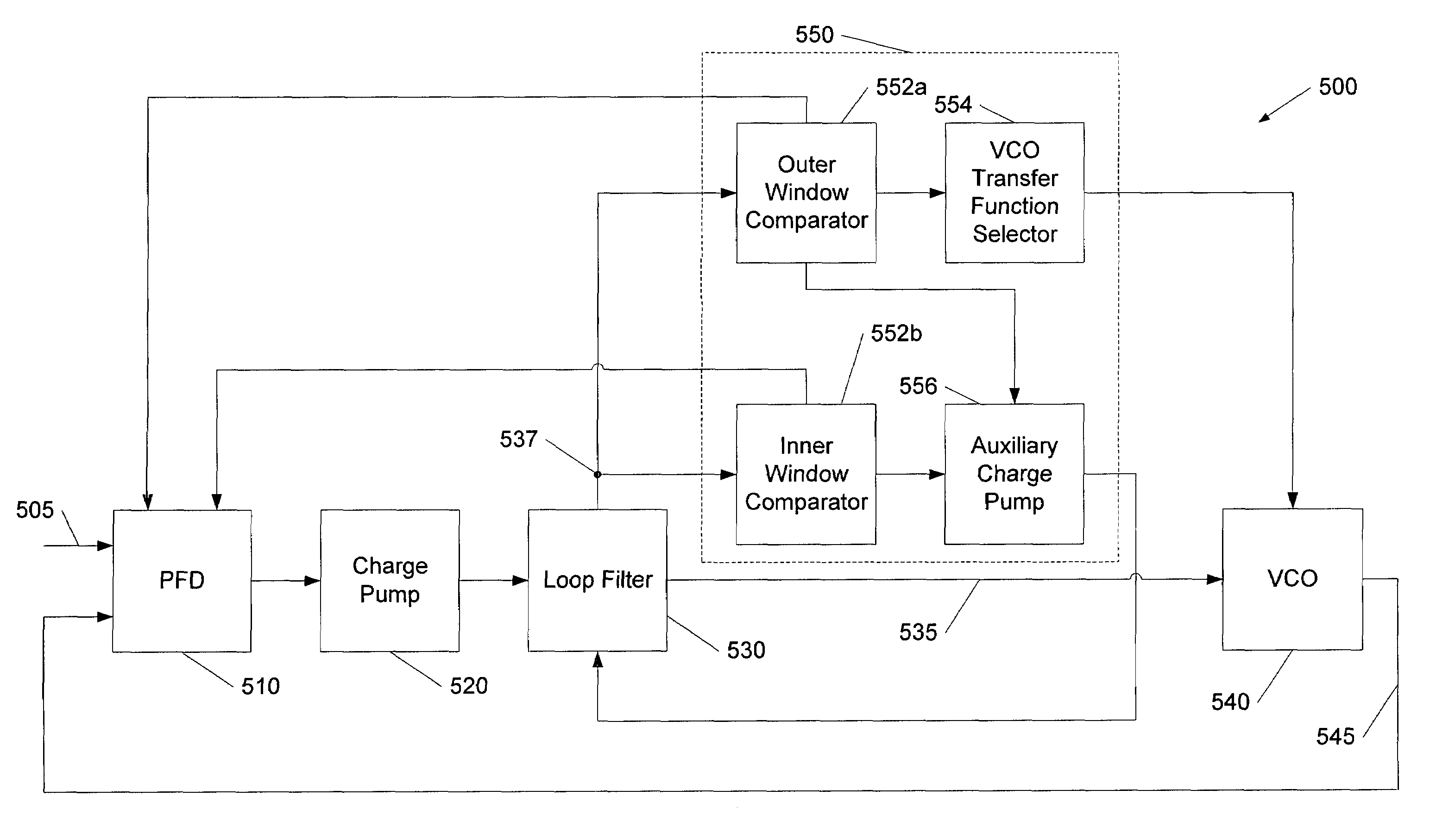
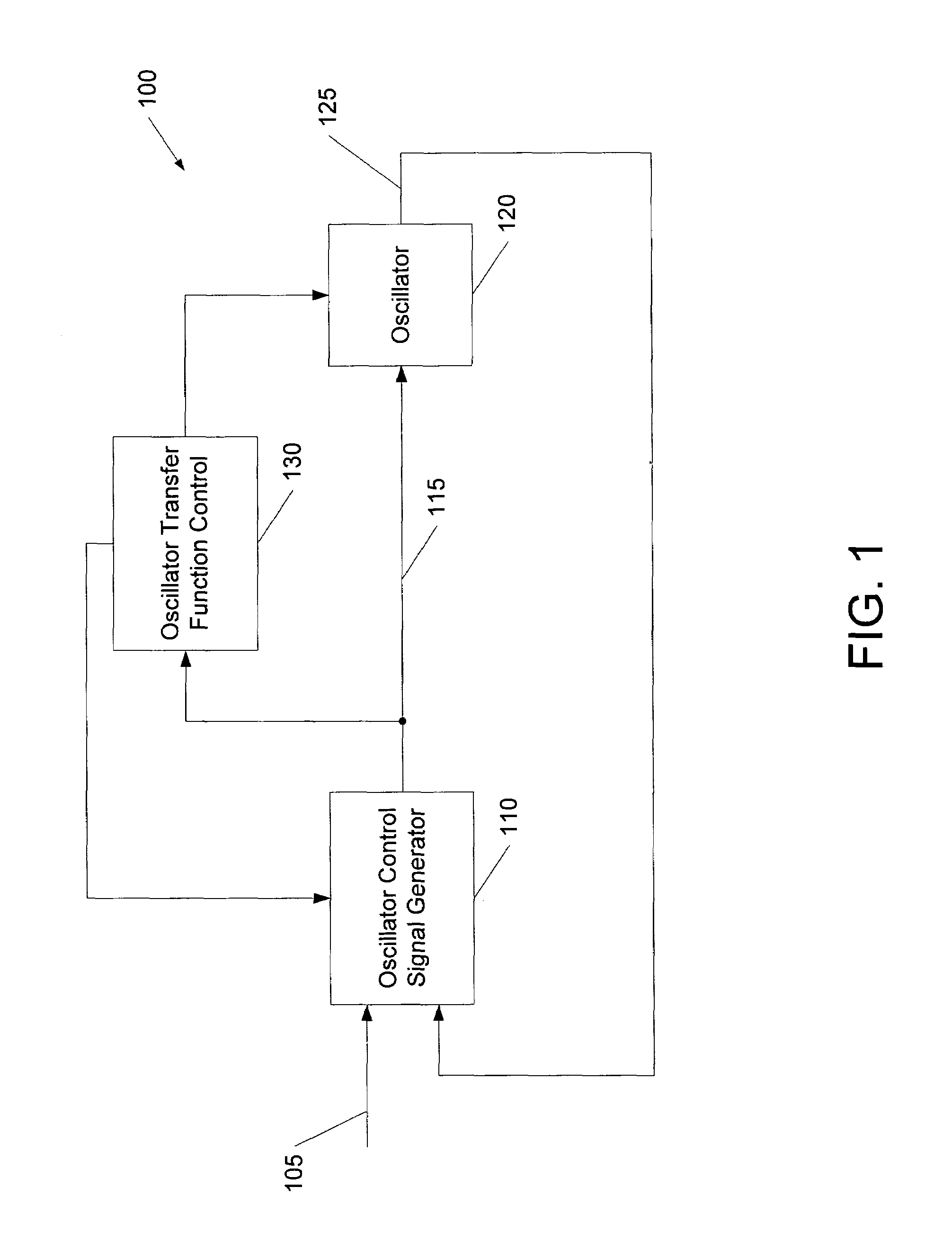
[0016]FIG. 1 illustrates a PLL circuit 100 according to some embodiments of the present invention. In particular, the PLL circuit 100 includes a controlled oscillator (e.g., a voltage controlled oscillator (VCO)) 120 that is controlled by an oscillator control signal 115 generated by an oscillato...


PUM


Abstract

A phase locked loop (PLL) circuit includes a controlled oscillator circuit that is operative to generate an output clock signal responsive to an oscillator control signal according to a plurality of selectable transfer functions, and an oscillator control signal generator circuit that is operative to generate the oscillator control signal responsive to the output clock signal and a reference clock signal. The PLL circuit further includes a transfer function control circuit operative to transition operation of the controlled oscillator from a first one of the transfer functions to a second one of the transfer functions responsive to the oscillator control signal. For example, the transfer function control circuit may step the controlled oscillator circuit through a succession of the transfer functions in response to a change in a frequency of the reference clock signal and may enable a closed loop including the oscillator control signal generator circuit and the controlled oscillator circuit upon selection of each of the succession of transfer functions.

Description

BACKGROUND OF THE INVENTION[0001]The present invention relates to clock generation circuits and methods of operation thereof, and more particularly, to phase locked loop (PLL) circuits and methods of operation thereof.[0002]PLL circuits are commonly used in clock generator circuits, such as clock buffers, that are used to generate precisely timed clock signals for distribution to various components of an electronic system. A PLL circuit typically comprises a closed loop that is used to synchronize an output clock signal with an input reference clock signal. It is generally desirable that a PLL be capable of generating an output signal that remains closely synchronized with its reference or master clock (i.e., with minimal jitter and high stability) over a range of temperatures and / or power supply voltages. It may also be desirable for the PLL to be capable of operation over a wide range of input reference clock signal frequencies.[0003]A common issue in designing PLLs is achieving a...

Claims


Application Information

Patent Timeline
Patent Type & Authority Patents(United States)
IPC IPC(8): H03L7/00
CPCH03L7/107H03L7/10H03L7/095Y10S331/02H03L7/102
Inventor MCDONAGH, DECLANMURTAGH, PAUL
Owner INTEGRATED DEVICE TECH INC
Why Eureka
Try Eureka