
Telescope mount having locator system and drive mechanism for locating objects and positioning telescope

a technology of locator system and drive mechanism, which is applied in the field of telescope mounts, telescope mounts, telescope mounts, etc., can solve the problems of large amount of inefficient and inconvenient repetition of large parts of the process, and the astronomer is not yet ready to begin observation, so as to reduce weight and cost

Inactive Publication Date: 2006-05-16
BUSHNELL CORPORATION
View PDF14 Cites 9 Cited by
  • Summary
  • Abstract
  • Description
  • Claims
  • Application Information

AI Technical Summary

Benefits of technology

"The present invention is a locator system that integrates a locator with a telescope mount to reduce weight and cost. It uses magnetic encoders and a microprocessor to locate objects and provide precise position data. The system is easy to use, with no complex configuration required. It allows for automatic or manual positioning of the mount and can track astronomical objects during extended viewing. The system provides a database of objects and their positions, which can be recalled and displayed for the user. The encoder data is translated into current position data, which can be displayed and stored in the microprocessor's memory. The system eliminates the need for complex calculations to determine or re-determine an object's position. The mount also includes a drive mechanism with a clutch mechanism for automatic or manual positioning and obstruction handling. Overall, the locator system provides a cost-effective and efficient solution for many applications, including high magnification observation and astrophotography."

Problems solved by technology

Having successfully mastered the complex spherical coordinate system, an astronomer is not yet ready to begin observation.
As can be appreciated, locating astronomical objects and positioning a telescope for observation can be a difficult, frustrating, and time consuming process.
Furthermore, once the telescope has been repositioned to observe a second object, a large part of the process must be inefficiently and inconveniently repeated to reacquire the first object.
Unfortunately, such automated systems are too expensive and cumbersome for use on small, portable telescopes.
For example, common optical encoders for position determination are too expensive or use impractically complex or heavy mechanical gears or similar mechanisms.
Furthermore, results of attempts to create a practical and economically feasible portable automated locator system for small telescopes have typically been sorely lacking in accuracy.
Unfortunately, any movement of the mount or telescope tube (e.g., resulting from incidental contact) that is not initiated by the microprocessor and implemented by the stepper motors can adversely affect the accuracy of the locator system.
Furthermore, because the stepper motor is always physically engaged with the mount, any manual movement of the mount or telescope tube is transferred to and may strain or otherwise damage the stepper motors.
Unfortunately, the drive motors remain physically engaged with the mount such that any manual movement of the mount or telescope tube is transferred to and may strain or otherwise damage the drive motors.

Method used


Image

  • Telescope mount having locator system and drive mechanism for locating objects and positioning telescope
  • Telescope mount having locator system and drive mechanism for locating objects and positioning telescope
  • Telescope mount having locator system and drive mechanism for locating objects and positioning telescope

Examples


Embodiment Construction

, below.

BRIEF DESCRIPTION OF THE DRAWING FIGURES

[0021]A preferred embodiment of the present invention is described in detail below with reference to the attached drawing figures, wherein:

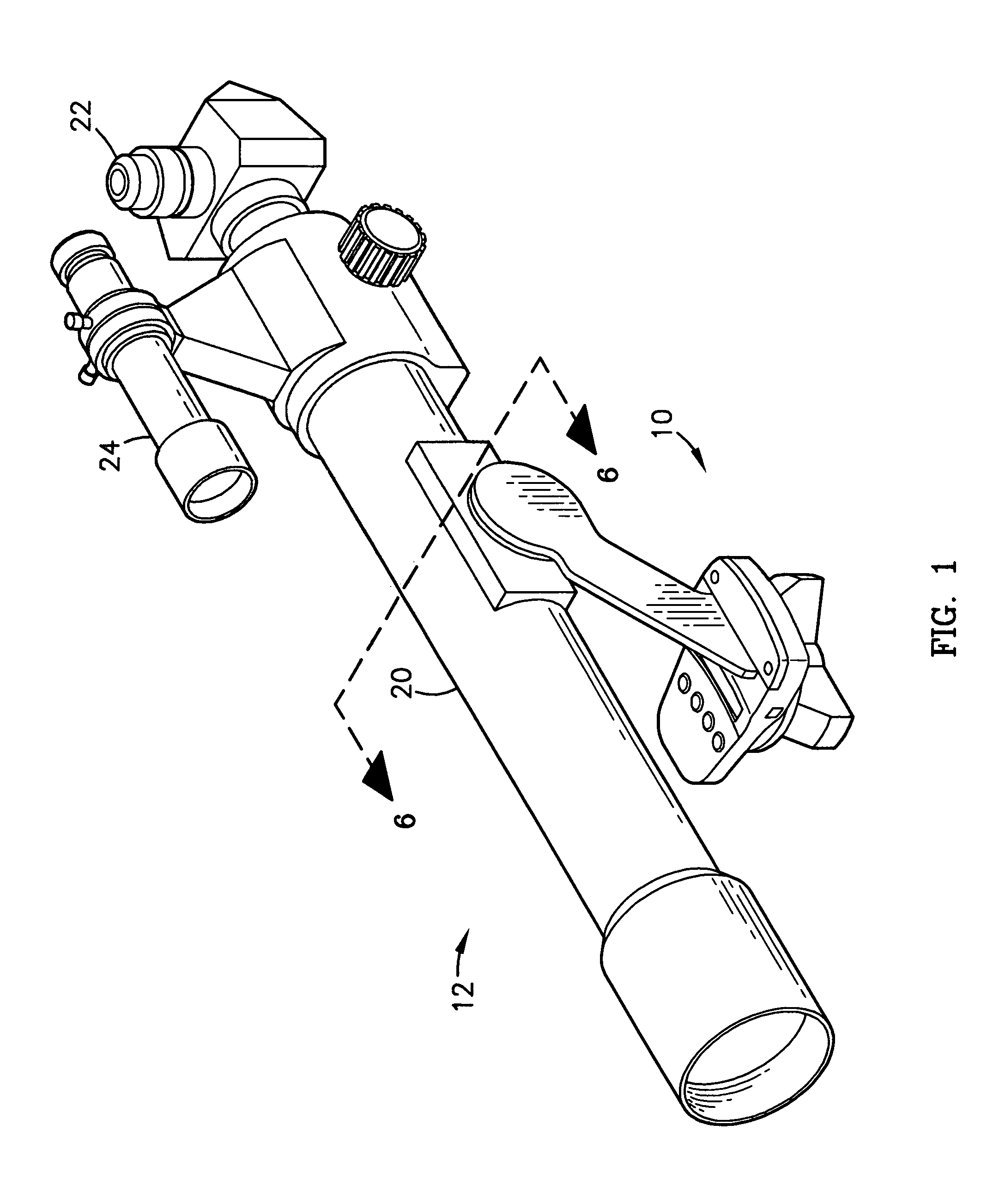
[0022]FIG. 1 is a first isometric view of a mount constructed in accordance with a preferred embodiment of the present invention, with the mount shown supporting a telescope;

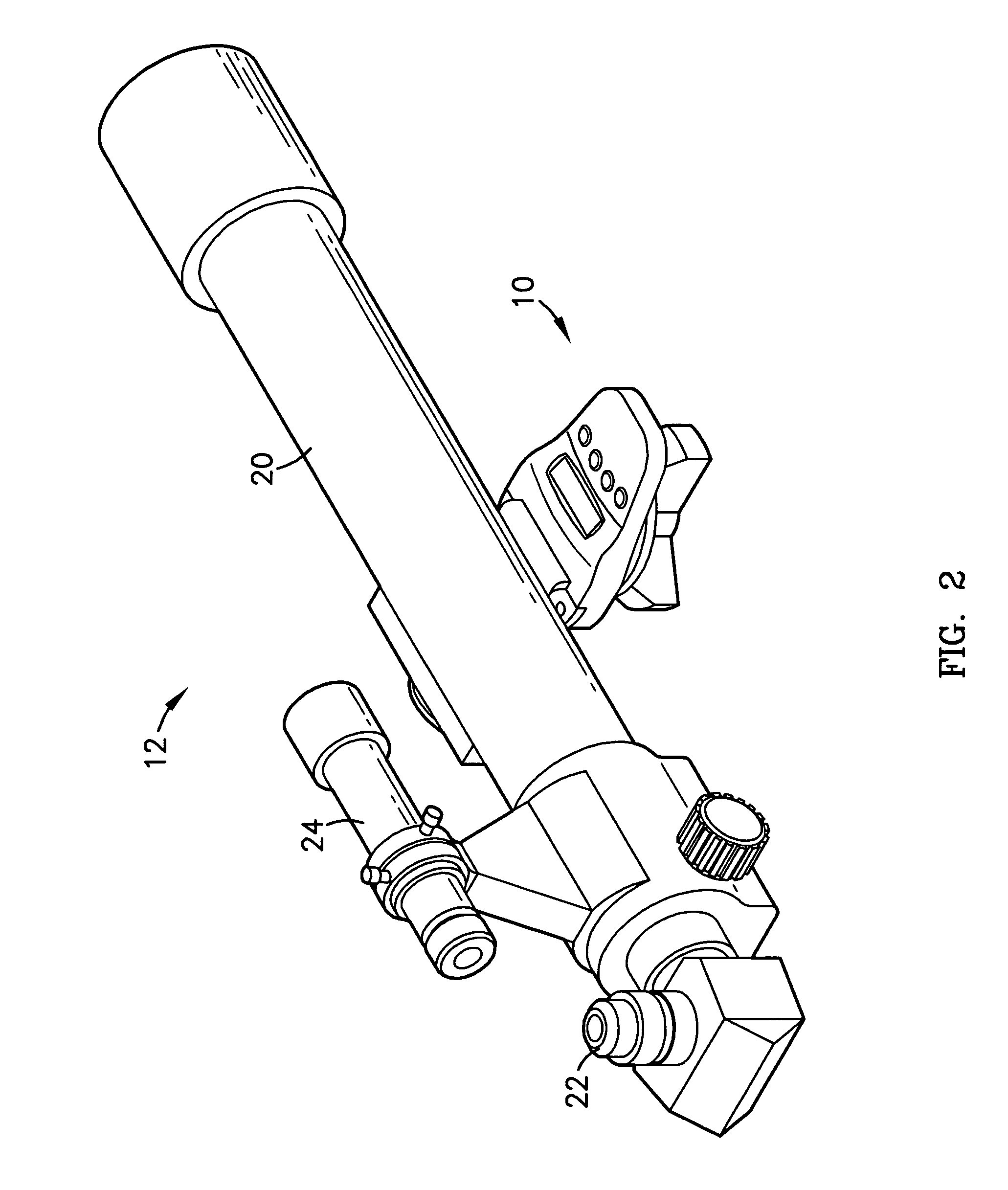
[0023]FIG. 2 is a second isometric view of the embodiment shown in FIG. 1;

[0024]FIG. 3 is an exploded view of a preferred embodiment of the present invention;

[0025]FIG. 4 is a representation of a component of a preferred embodiment of the magnetic encoder portion of the present invention;

[0026]FIG. 5 is a representation of the structural and operational relationship between components of a preferred embodiment of the magnetic encoder portion of the present invention;

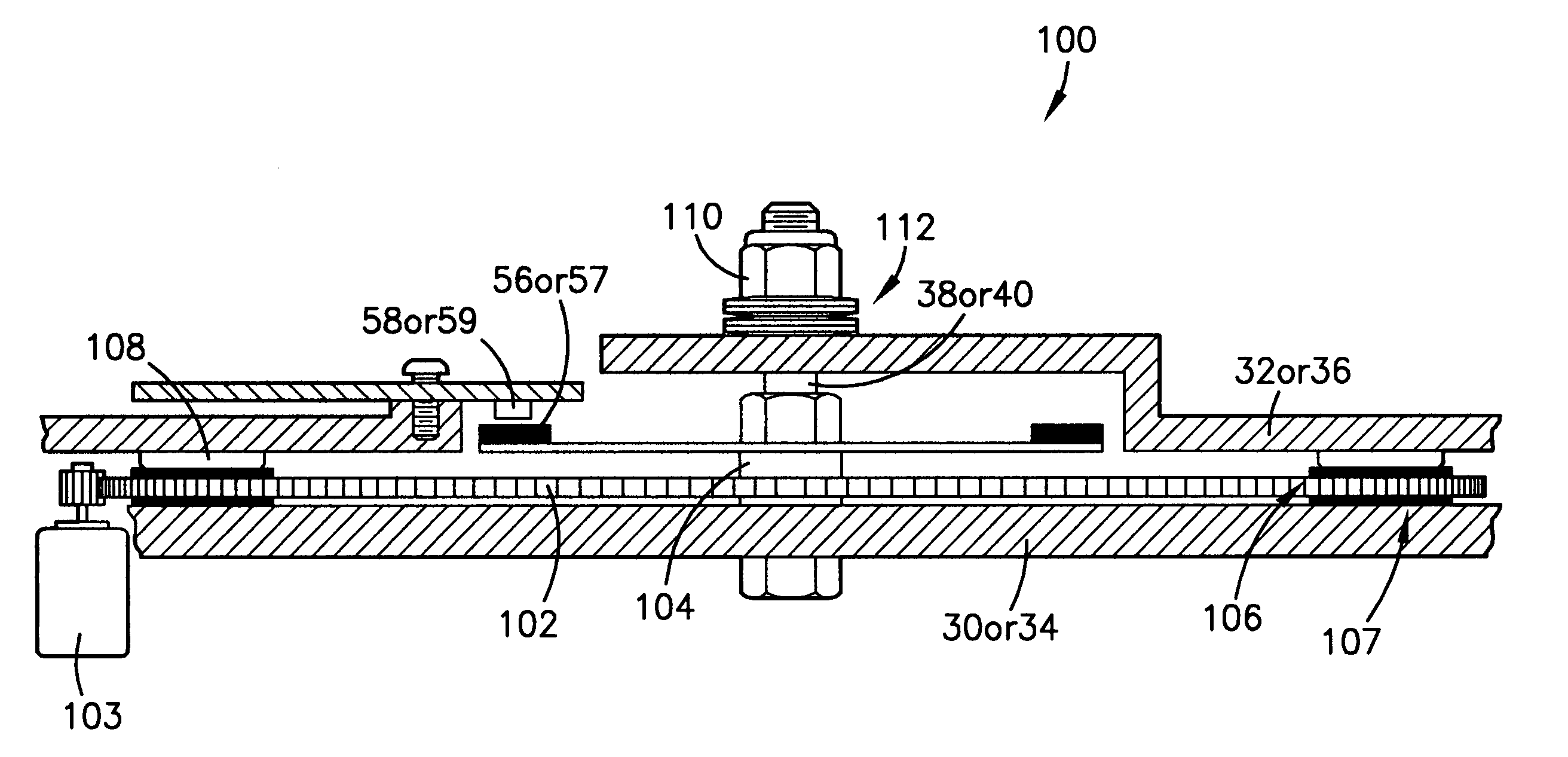
[0027]FIG. 6 is a fragmentary, vertical cross-sectional, elevation view through the line 6—6 of FIG. 1 and illustrating two substantially identical drive mechanisms ...


PUM


Abstract

A portable altitude / azimuth telescope mount having an integral locator system with a magnetic encoder mechanism for facilitating location of astronomical objects and telescope positioning for observation thereof. A microprocessor receives signals from the encoder mechanism and translates such into position data for display. The locator system also includes a database of astronomical objects, including their locations and other relevant information. The mount is preferably provided with a drive mechanism adapted to allow for automatically or manually positioning the telescope to view astronomical objects and for automatically repositioning or steering the telescope in order to track the astronomical objects during extended viewing. When moved manually, components of the drive act as a clutch mechanism that effectively disengages the drive motor to avoid damage. An instance of the drive may be provided for each axis of movement.

Description

RELATED APPLICATIONS[0001]The present patent application is a continuation-in-part and claims priority benefit with regard to all common subject matter of an earlier-filed patent application titled A PORTABLE TELESCOPE MOUNT WITH INTEGRAL LOCATOR USING MAGNETIC ENCODERS FOR FACILITATING LOCATION OF OBJECTS AND POSITIONING OF A TELESCOPE, Ser. No. 09 / 780,822, filed Feb. 9, 2001, now U.S. Pat. No. 6,603,602. The identified earlier-filed patent application is hereby incorporated by reference into the present patent application.COMPUTER PROGRAM LISTING APPENDIX[0002]A computer program listing appendix containing the source code of a computer program that may be used with the present invention is incorporated herein by reference and appended hereto as one (1) original compact disk, and an identical copy thereof, containing a total of two (2) files as follows:[0003]Filename:Date of Creation:Size:INTSF3.TXTAug. 04, 2003 10:36 p.m.106 KBSF3.TXTAug. 04, 2003 10:36 p.m.379 KBBACKGROUND OF THE...

Claims


Application Information

Patent Timeline
Patent Type & Authority Patents(United States)
IPC IPC(8): G02B23/00G05B19/29G02B7/12G02B23/16
CPCG02B23/16G02B7/12
Inventor MCWILLIAMS, RICK
Owner BUSHNELL CORPORATION
Learn More