Optical fiber coupling configurations for a main-remote radio base station and a hybrid radio base station

a technology of optical fiber and hybrid radio, applied in the field of radio communication, can solve the problems of different optical link delays, time/phase shift of signals, and delay that is not constant and may vary, so as to avoid the expense and drawbacks, eliminate the cost necessary, and avoid the effect of cost and cos

Inactive Publication Date: 2006-05-16
TELEFON AB LM ERICSSON (PUBL)
View PDF24 Cites 144 Cited by
  • Summary
  • Abstract
  • Description
  • Claims
  • Application Information

AI Technical Summary

Benefits of technology

[0003]Some mobile communication standards, e.g., the code division multiple access (CDMA) cellular system, permit a UE to communicate with two or more RRUs of the same base station using “softer handover.” In softer handover, two or more RRUs simultaneously transmit the same information to the UE and receive the same information from the UE. The simultaneously transmitted signals must be processed to generate a single signal. Some radio standards require that in the downlink direction, the signals simultaneously transmitted to the UE from different antennas be aligned with a timing reference at the antennas. That alignment makes combining those different signals easier on the receiver. In the uplink direction, the main unit base band functionality includes a rake receiver which combines the “same” signals received from the UE via the RRUs and generates a single signal. Because of differing path lengths to each RRU, these signal components received at the main unit base band functionality from different radio remote units are not time and phase aligned to each other. Although a rake receiver can combine out-of-phase signals from different signal paths, a less complicated and less expensive rake receiver may be used if the phase / delay differences between different signal paths are kept small.
[0020]The present invention provides a cost effective optical fiber configuration to couple a base station main unit and plural base station remote units. Only a single optical fiber loop is needed to carry information between the main unit and the remote units. The configuration avoids the expense and drawbacks if WDM technology were used in a single fiber loop configuration. Lasers, filters, and optical add / drop multiplexers (OADMs) for each RRU are not needed thereby eliminating costs necessary for a WDM fiber loop configuration. The logistical WDM overhead required to keep track of different wavelength dependent devices is also avoided. In addition to cost savings, the invention compensates for time delay differences associated with different remote units coupled in series by a single fiber to ensure synchronization.

Problems solved by technology

Different optical link delays are more problematic as the distance between the remote unit 16 and the main unit increases, e.g., 10 kilometers.
In addition, such delays are not constant and may vary depending on temperature and other factors.
Without compensation, the different optical fiber lengths to the remote units result in a time / phase shift of the signals sent out from the antennas connected to the radio remote units.
They also lead to larger time / phase shifts between the UE signal components received via different radio remote units.
These time / phase shifts may be difficult for conventional receivers in the UE and in the base station to handle.
A similar problem exists in a hybrid base station that incorporates both conventional near radio units and remote radio units.
Another challenge in main-remote configurations is how best to connect the main and remote units.
But the amount of fiber required is significant—as is the cost for separate main unit—RRU fiber loops.
The cost of the laser and detector equipment associated with each fiber pair in the main unit is also significant.
A drawback with this approach is the expense of WDM technology including lasers, filters, and OADMs.
Another is logistical overhead to keep track of different wavelength dependent devices.

Method used


Image

  • Optical fiber coupling configurations for a main-remote radio base station and a hybrid radio base station
  • Optical fiber coupling configurations for a main-remote radio base station and a hybrid radio base station
  • Optical fiber coupling configurations for a main-remote radio base station and a hybrid radio base station

Examples


Embodiment Construction

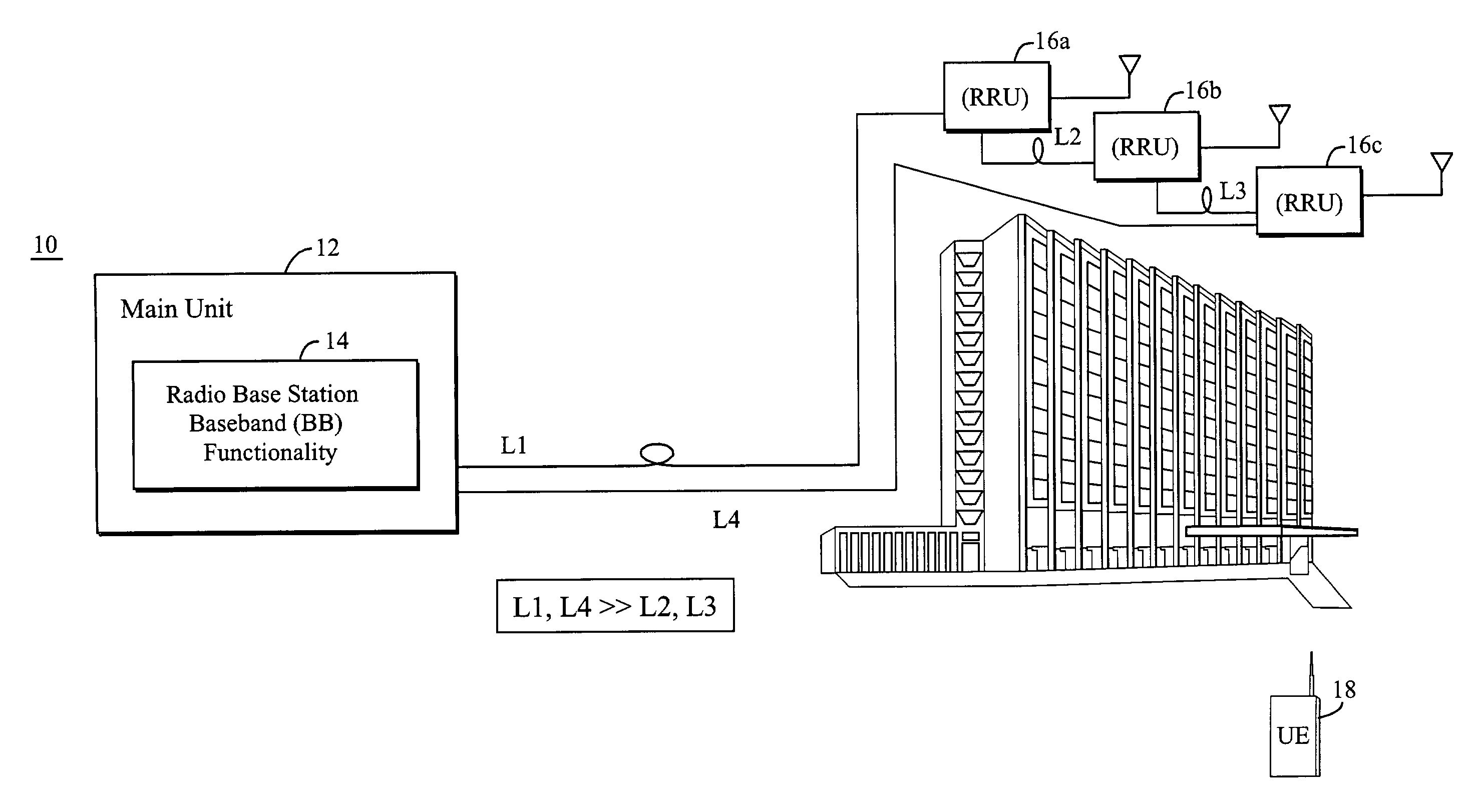
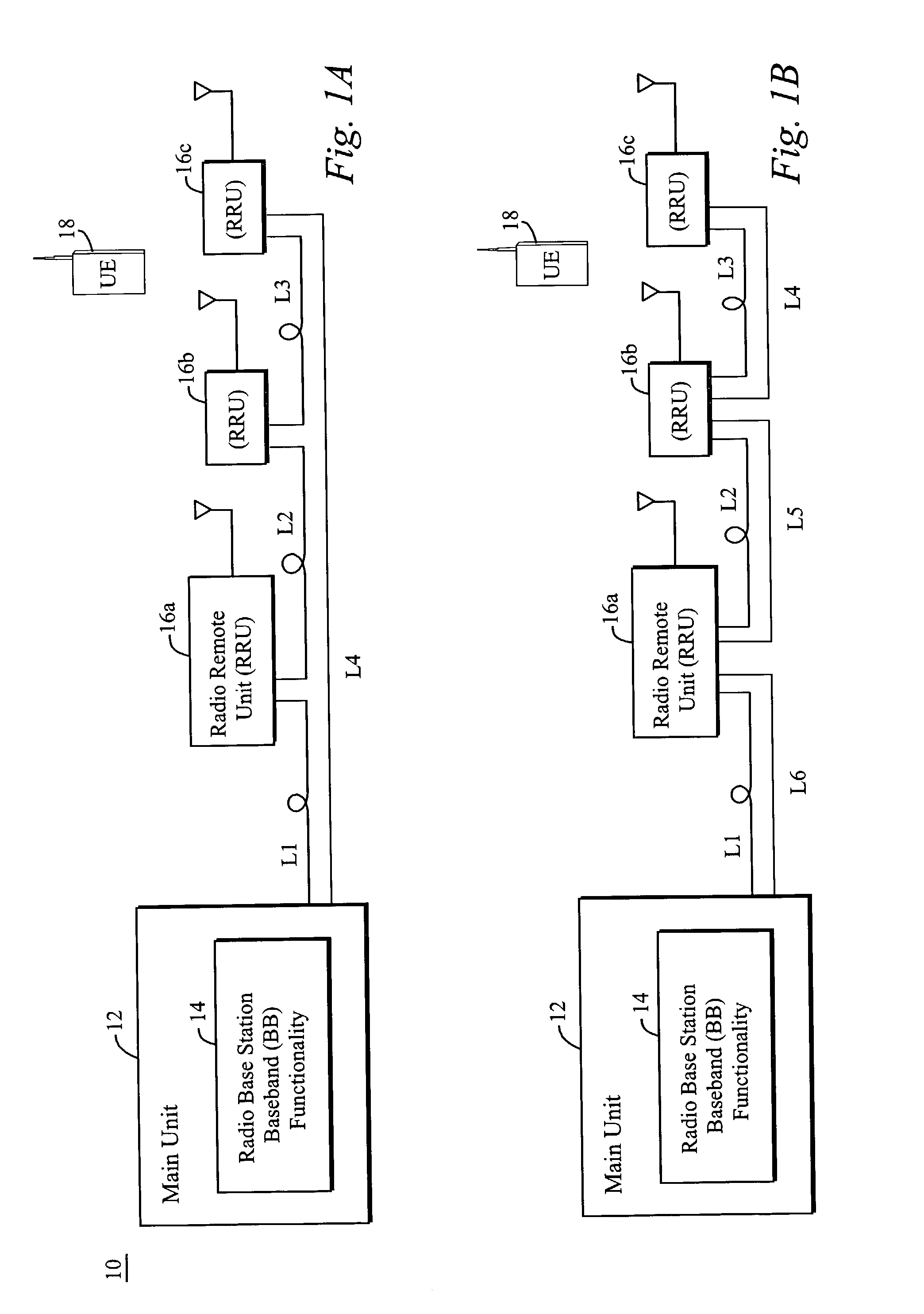
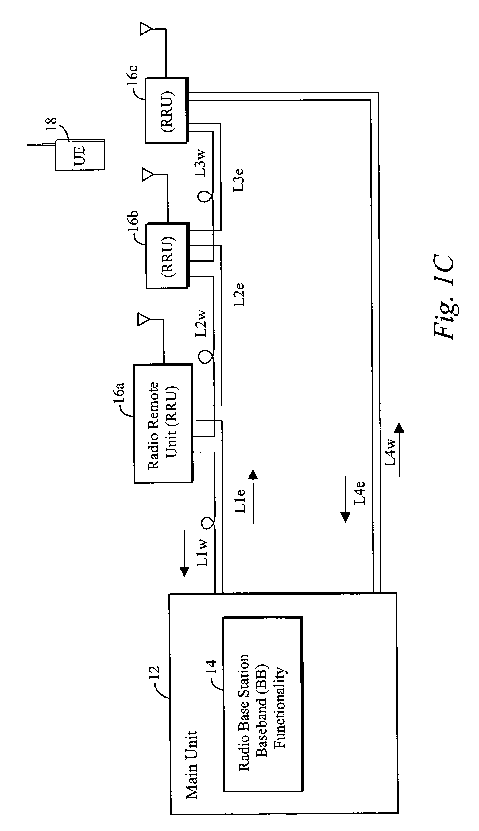
[0033]In the following description, for purposes of explanation and not limitation, specific details are set forth, such as particular embodiments, procedures, techniques, etc. in order to provide a thorough understanding of the present invention. However, it will be apparent to one skilled in the art that the present invention may be practiced in other embodiments that depart from these specific details. For example, while the present invention is described in an example application to a CDMA-based cellular system, the present invention may be used in any cellular system employing a main-remote radio base station architecture having any number of remote units configured in any network topology where plural RRUs can be coupled in an optical fiber loop. It may also be used in any cellular system employing a hybrid base station. Although some of the following examples employ a single fiber loop, the invention may also be used in coupling configurations that use plural fibers.

[0034]In ...


PUM


Abstract

A main-remote radio base station system includes plural remote radio units. Fiber costs are significantly reduced using a single optical fiber that communicates information between the main unit and the remote units connected in a series configuration. Information from the main unit is sent over a first fiber path to the remote units so that the same information is transmitted over the radio interface by the remote units at substantially the same time. The main unit receives the same information from each of the remote units over a second fiber path at substantially the same time. Delay associated with each remote unit is compensated for by advancing a time when information is sent to each remote unit. A data distribution approach over a single fiber avoids the expense of separate fiber couplings between the main unit and each RRU. That approach also avoids the expense of WDM technology including lasers, filters, and OADMs as well as the logistical overhead needed to keep track of different wavelength dependent devices.

Description

FIELD OF THE INVENTION[0001]The present invention is directed to radio communications where a base station includes a main baseband processing unit and plural radio remote units where RF processing occurs.BACKGROUND AND SUMMARY OF THE INVENTION[0002]A conventional radio base station in a cellular communications system is generally located in a single location, and the distance between the baseband circuitry and the radio circuitry is relatively short, e.g., on the order of one meter. A distributed base station design, referred to as a main-remote design, splits the baseband part and the radio part of the base station. The main unit (MU) performs base band signal processing, and one or more radio remote units (RRUs) converts between baseband and radio frequencies and transmits and receives signals over one or more antennas. Each RRU serves a certain geographic area or cell. Separate, dedicated optical links connect the main unit to each of the plural radio remote units. Each optical ...

Claims


Application Information

Patent Timeline
Patent Type & Authority Patents(United States)
IPC IPC(8): H04B15/00H04B10/12
CPCH04B10/25758H04B10/25755H04B17/19
Inventor CAGENIUS, TORBJORN
Owner TELEFON AB LM ERICSSON (PUBL)
Why Eureka
Try Eureka