Iontophoretic fluid delivery device

a technology of electrotransport device and ionophoretic fluid, which is applied in the direction of medical devices, other medical devices, therapy, etc., can solve the problems of compromising treatment, high cost of power module, and inherently long treatment time intervals, and achieves fast and accurate results

Inactive Publication Date: 2006-05-16
ACTIVATEK
View PDF38 Cites 27 Cited by
  • Summary
  • Abstract
  • Description
  • Claims
  • Application Information

AI Technical Summary

Benefits of technology

[0011]The invention provides an apparatus and method for delivering a treatment to a body by way of an iontophoretic transport procedure. A device constructed according to principles of the instant invention provides a low-cost, disposable, single-use, fast and accurate, iontophoretic fluid delivery device for external or implantable use. A body may be construed specifically as a mammalian (e.g., human or animal) body or, alternatively and generally, as a container of an electrolyte. A treatment to be applied to a body by the instant device and method may be either cationic-based or anionic-based.
[0013]Treatment materials may be loaded, by syringe or other transfer mechanism, onto a substrate housed within a chamber. Substrates desirably may be configured to reduce polarization of the treatment materials with an attendant drop in reaction rate. One such configuration includes an electrically conductive substrate affixed to a wall of one of the chambers. A workable such substrate may have a surface area, for electron transfer, sized substantially in correspondence with an opening of an ion transfer passageway. An alternate substrate may be formed as an electrically conductive gauze. The conductive gauze may be dispersed substantially throughout the volume of the chamber. A hydrogel substance operable as an electrolyte can be disposed, substantially as a preloaded item, in one or both of the cationic or anionic chambers. Such a preloaded hydrogel can reduce preparation time of a treatment by requiring only the treatment to be introduced, and only to a single chamber of the container.
[0017]Certain preferred iontophoretic devices may use one or more electromotive cells, as required, e.g., to control a length of time for, or rate of, delivery of a quantity of a treatment ion to a body. Such cells may be located partially or completely inside either one or both chambers, or attached to the container in some convenient location. In addition to providing treatment control through their inherent operating life, cells may be arranged in series to provide an increased voltage over a single cell. The increased voltage may permit a reduction in a time of treatment application.
[0020]Additional circuit components may be included in the second conductive path to increase treatment options and efficacy. As a non-limiting example, an oscillator element can be disposed in-circuit in the second conductive path and operate to control a current flow between high and low values. A switch placed in the second path may be used to start and stop treatments at controlled intervals.

Problems solved by technology

Such devices inherently require long treatment time intervals.
While treatment time requirements for devices having auxiliary power modules are generally reduced, the power modules are expensive and so typically must be reused.
In use of a device 30, there is some possibility that a desired treatment chemical may undesirably interact with the electrolyte, electrode, or a product of the galvanic reaction, thereby compromising a treatment.
Additional cells may be added in series; however, the adhesive strip 33 rapidly becomes crowded, thereby limiting the practical range in electromotive force for a device 30.
A power module 63 typically houses sophisticated electronics and is relatively expensive (power modules are generally not regarded as single-use, disposable items).
However, power modules 63 represent an expense and may cause inconvenience in that operators may require special expertise to properly configure the module for a particular treatment.

Method used


Image

  • Iontophoretic fluid delivery device
  • Iontophoretic fluid delivery device
  • Iontophoretic fluid delivery device

Examples


Embodiment Construction

[0038]Reference will now be made to the drawings in which the various elements of the invention will be given numerical designations and in which the invention will be discussed so as to enable one skilled in the art to make and use the invention. It is to be understood that the following description is only exemplary of the principles of the present invention and should not be viewed as narrowing the claims which follow.

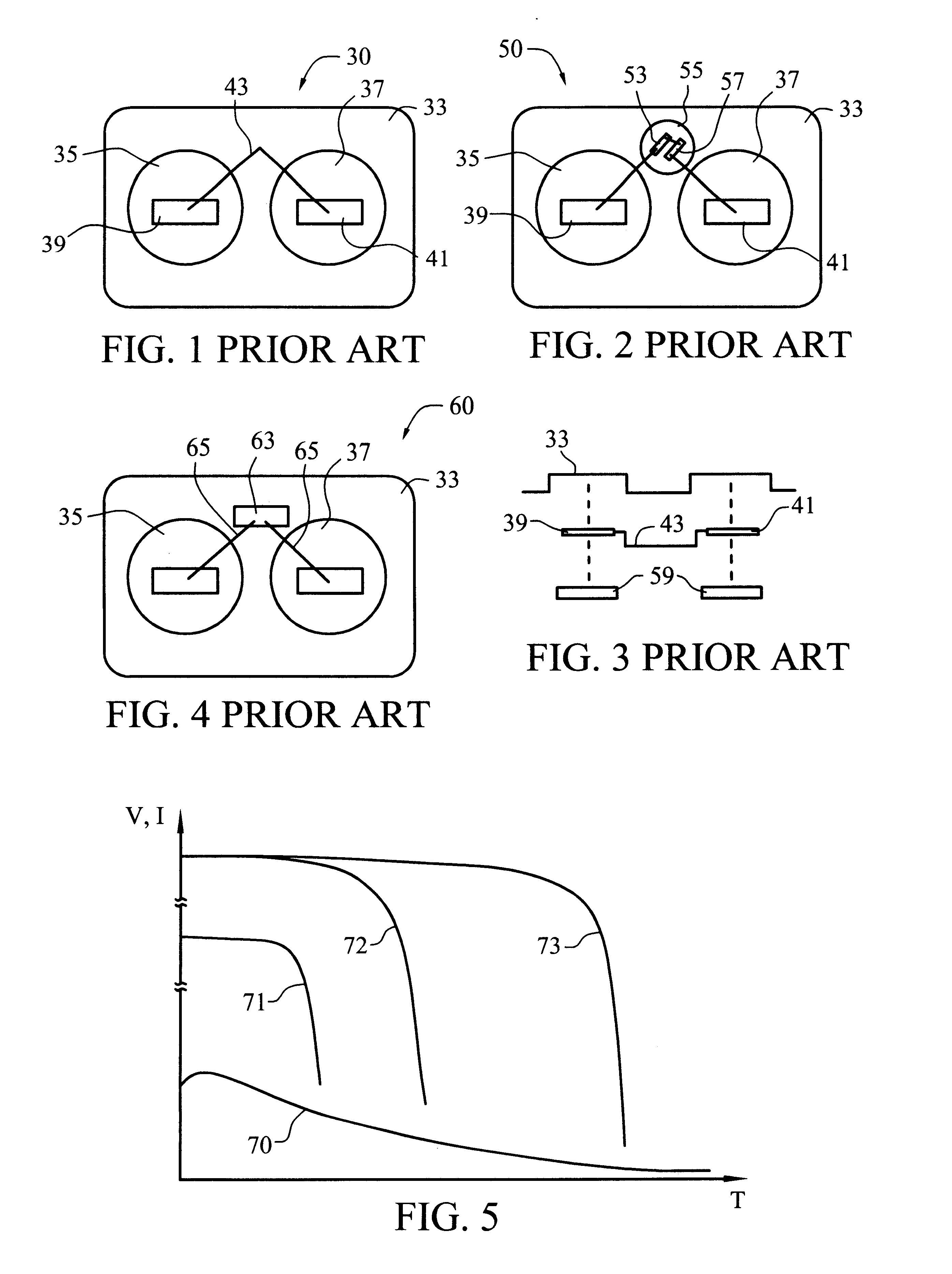
[0039]A plot of current discharge or voltage verses time is presented in FIG. 5, with the horizontal axis indicating a time scale and the vertical axis showing either a current flow or available voltage. Trace line 70 is representative of a current profile obtainable in a commercially available and disposable galvanic cell device, such as device 30. Trace line 70 shows a reduced current flow over time due to polarization of electrolyte in the areas surrounding the electrodes and a corresponding reduced rate of chemical reaction. Trace lines 71-73 are achievable in m...


PUM


Abstract

A low cost, accurate, single use, disposable, iontophoretic fluid delivery device having cationic and anionic chambers separated by container structure and arranged to promote a flow of treatment ions into a body. The device desirably uses rugged minibatteries safely to provide increased electromotive force to the ion transfer process compared to galvanic cells having electrolyte matched to a human body's electrolyte. Minibatteries may be located in one or both cationic and anionic chambers, and / or attached to structure of a container outside the chambers. A shunt resistance may be arranged in a parallel circuit to the body to control delivery of a beneficial agent in any amount between 1 mAmp-min to 500 mAmp-min, or more. Substrates, located in the chambers and adapted to hold electrolyte or treatment drugs, may be electrically conductive to resist polarization of the chemicals near a conducting terminal. Cationic and anionic chambers may be made having different sizes and / or shapes to facilitate placement of treatment drugs into the correct chamber.

Description

TECHNICAL FIELD[0001]The present invention relates to apparatus and methods for delivering drugs or other beneficial agents. More specifically, the present invention relates to iontophoretic electrotransport devices and methods of their use in delivering treatment to a body.BACKGROUND[0002]Iontophoretic transport of drug or biological treatments is well known and is commonly used as one way to transport such treatments across a surface and into a body. Many iontophoretic devices have been developed, as witnessed by the quantity of issued patents and pending applications mentioning such phenomena. A representative such application, titled “Rate Adjustable Drug Delivery System” filed by Birch Point Medical, Inc., was published Jul. 12, 2001 as international publication No. WO 01 / 49365 A1. The '49365 application is hereby incorporated by this reference as though set forth in full herein.[0003]Existing iontophoretic devices may generally be classified into two groups based upon their el...

Claims


Application Information

Patent Timeline
Patent Type & Authority Patents(United States)
IPC IPC(8): A61N1/30A61M31/00A61N1/00
CPCA61N1/0428A61N1/0448A61N1/306
Inventor JOSHI, ASHOK V.
Owner ACTIVATEK
Why Eureka
Try Eureka