Protection scheme and method for deployment of artificial lift devices in a wellbore

a protection scheme and wellbore technology, applied in the direction of wellbore/well accessories, fluid removal, sealing/packing, etc., can solve the problems of static, or backup, unit sitting idle, and/or blocking of flow passageways, and/or interference or locking of rotating components

Inactive Publication Date: 2006-05-23
BAKER HUGHES INC
View PDF18 Cites 31 Cited by
  • Summary
  • Abstract
  • Description
  • Claims
  • Application Information

AI Technical Summary

Benefits of technology

[0014]The present invention features an artificial lift device that is suspended on a flow conduit within a well. The artificial lift device is submerged in well fluids. A barrier is provided to prevent ingress of well fluids into the artificial lift device.

Problems solved by technology

One difficulty is that the static, or backup, unit sits idle and soaks in the wellbore environment, where the backup unit may be exposed to pressure cycles and possibly small temperature cycles.
This can cause plugging of flow passageways and / or interference or locking of rotating components.

Method used


Image

  • Protection scheme and method for deployment of artificial lift devices in a wellbore
  • Protection scheme and method for deployment of artificial lift devices in a wellbore
  • Protection scheme and method for deployment of artificial lift devices in a wellbore

Examples


Embodiment Construction

[0032]Before explaining the present invention in detail, it is important to understand that the invention is not limited in its application to the details of the embodiments and steps described herein. The invention is capable of other embodiments and of being practiced or carried out in a variety of ways. It is to be understood that the phraseology and terminology employed herein is for the purpose of description and not of limitation.

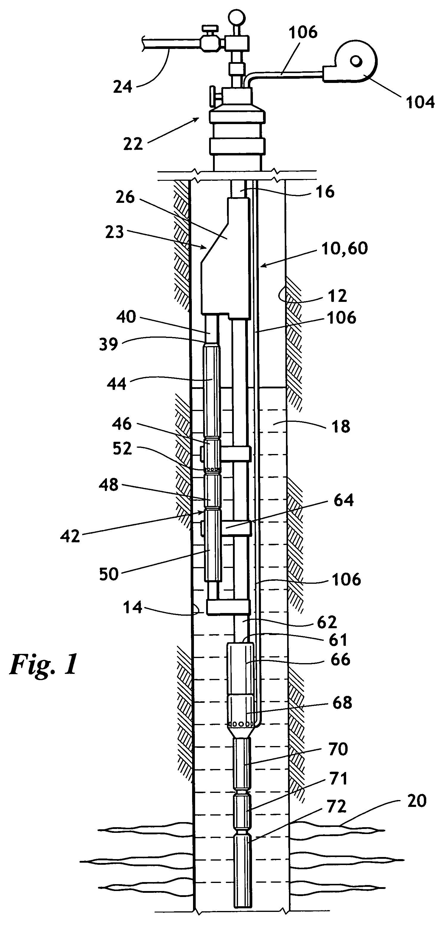
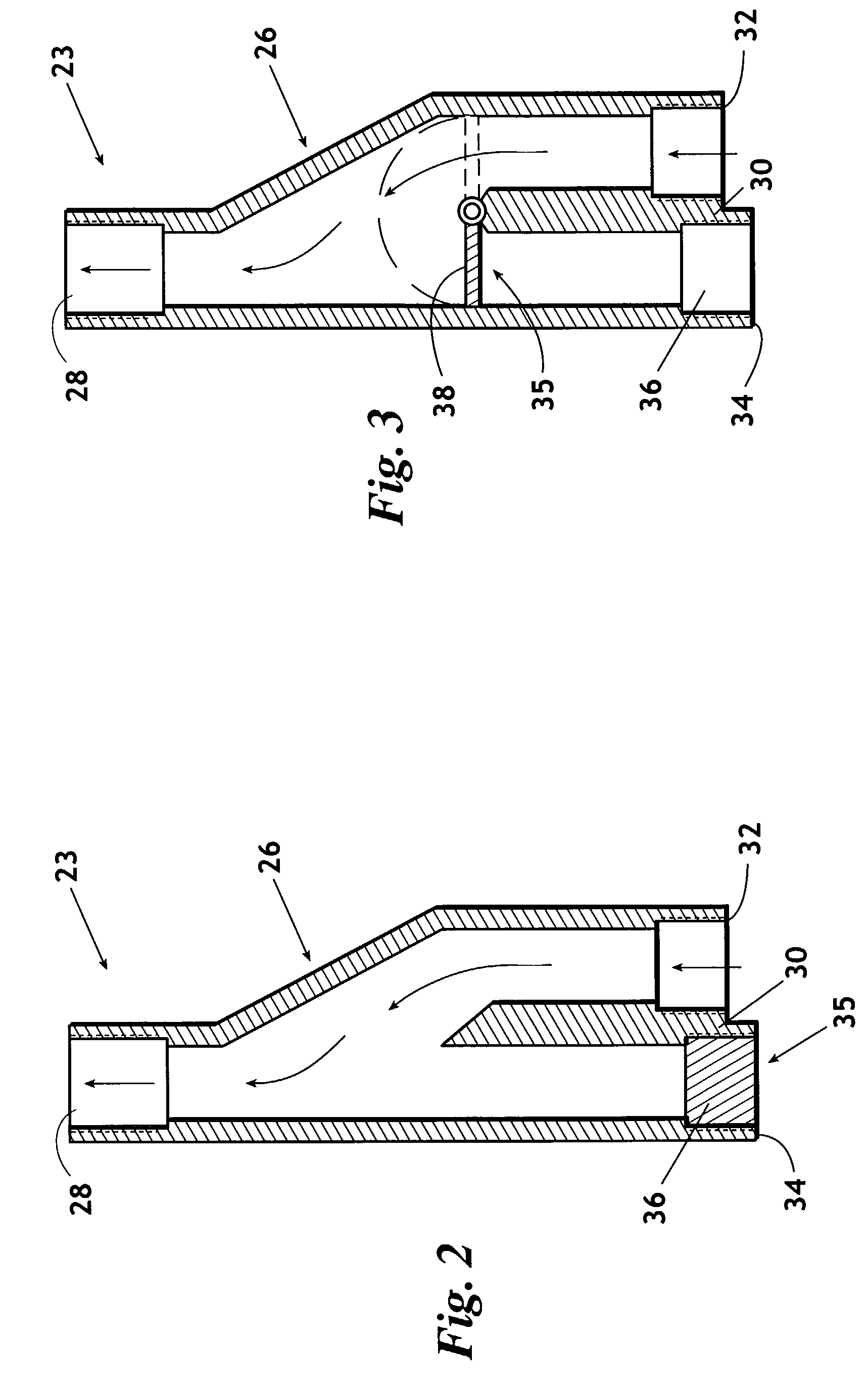
[0033]Referring now to FIG. 1, shown is a multiple unit system designated generally 10. The multi-unit system 10 is deployed within wellbore 12. Wellbore 12 is lined with casing 14. A tubing string 16 carries the multiple unit system 10. Typically, the multiple unit system 10 is utilized to lift wellbore fluids 18 that enter the wellbore 12 through perforations 20. Wellbore fluids 18 are directed upward through tubing string 16, through wellhead 22, and to a production line 24. A junction, designated generally 23, such as Y-Tool crossover 26, is affix...


PUM


Abstract

A protection system for an artificial lift device including but not limited to electrical submersible pump (ESP) and an electrical submersible progressing cavity pup (ESPCP). The artificial lift device is suspended on a tubing string into a wellbore where the artificial lift device contacts well fluids. The artificial lift device is provided with a barrier such as an intake barrier or output barrier that deters an ingress of well fluids into the artificial lift device. As a result, the artificial lift device may remain idle and submerged within well fluids for an extended period of time without experiencing degradation of the artificial lift device internals. The intake barrier may include a plug, burst disk, dissolvable material, a selectively openable barrier such as a sleeve or a spring biased member or other member that is capable of providing a suitable barrier. The barrier may be removed once the artificial lift device is ready for operation. The artificial lift device may be filled with a protective fluid. An optional pressure sensor may be provided that is in communication with the interior of the backup unit for communicating with a compressor that may be activated to maintain a positive pressure within the artificial lift device to prevent well fluids from entering the unit. The protection system of the invention is desirable for protecting an idle artificial lift device, including when the artificial lift device is a backup unit in a multi-artificial lift device deployment.

Description

BACKGROUND OF THE INVENTION[0001]1. Field of the Invention[0002]This invention relates generally to submersible artificial lift devices, and in particular to a single or multi-device system provided with a barrier to deter an ingress of well fluids into the device to reduce or prevent development of corrosion, formation of scale or asphaltenes or other problems in an idle device within a wellbore.[0003]2. Background[0004]Submersible artificial lift devices are widely used to pump fluid from a wellbore, particularly for purposes of hydrocarbon recovery. Examples of submersible artificial lift devices include an electrical submersible well pump (ESP) and an electrical submersible progressing cavity pump (ESPCP). Typically, an artificial lift device is suspended within a well from a flow conduit. The artificial lift device is submerged in well fluids. Prolonged inactivity and exposure to well fluids may damage motor and pump components of a typical artificial lift device. Therefore, it...

Claims


Application Information

Patent Timeline
Patent Type & Authority Patents(United States)
IPC IPC(8): E21B34/00E21B41/02E21B43/12
CPCE21B43/128E21B41/02
Inventor BEARDEN, JOHN L.RIDER, JERALD R.
Owner BAKER HUGHES INC
Why Eureka
Try Eureka