Projection optical system, magnification projection optical system, magnification projection apparatus, and image projection apparatus

a projection optical system and magnification projection technology, applied in projectors, instruments, focusing aids, etc., can solve the problems of chromatic aberration generation, image optical systems composed of only reflecting surfaces cannot correct chromatic aberration, and so on

Active Publication Date: 2006-05-23
RICOH KK
View PDF53 Cites 146 Cited by
  • Summary
  • Abstract
  • Description
  • Claims
  • Application Information

AI Technical Summary

Benefits of technology

[0020]Accordingly, it is a general object of the present invention to provide a projection optical system, a magnification projection optical system, a magnification projection apparatus, and an image projection apparatus in which the above-described disadvantages are eliminated.
[0021]A more specific object of the present invention is to provide a projection optical system, a magnification projection optical system, and a magnification projection apparatus that can increase a projection screen in size, employ an imaging optical system including a reflecting surface to reduce a projection space outside a projection apparatus, and at the same time, correct chromatic aberration.

Problems solved by technology

In the case of displaying images of red, green, and blue separately, using three light valves instead of a single light valve, and combining the separate images on a screen, the intervention of a color combining part such as a cross prism or a Philips prism is necessary, thus resulting in the generation of chromatic aberration at the time of combining colors.
However, the imaging optical system composed of only reflecting surfaces cannot correct chromatic aberration.
Therefore, the optical path length of the imaging light beam differs between the upper side and the lower side of the center part of the magnified projected image on the screen (corresponding to the center part of the image display panel), thus resulting in the generation of a so-called “trapezoidal distortion.”
The trapezoidal distortion is correctable by “keystone correction,” which, however, is likely to degrade the quality of the magnified image on the screen.
This, however, requires stricter shape accuracy and stricter assembly tolerance of the convex mirror, and also increases distortion.
As the distance between the imaging lens system and the convex mirror increases, however, the convex mirror becomes larger in size to increase its cost.
Further, the magnification projection apparatus is also likely to become larger in size.

Method used


Image

  • Projection optical system, magnification projection optical system, magnification projection apparatus, and image projection apparatus
  • Projection optical system, magnification projection optical system, magnification projection apparatus, and image projection apparatus
  • Projection optical system, magnification projection optical system, magnification projection apparatus, and image projection apparatus

Examples


embodiment 6

[0201]As shown in Embodiment 6 described below, the first reflecting mirror 131 has negative-power and is axially symmetric, and the second reflecting mirror 132 is an anamorphic polynomial free-form surface whose vertical power and lateral power are different. A light beam from the second reflecting mirror 132 is guided to the projection surface at an angle to the normal of the projection surface.

[0202]The transmission dioptric system 120 is decentered with respect to the normal of the projected object surface. The transmission refractive elements 121 through 127 of the transmission dioptric system 120, however, are not decentered with respect to one another.

[0203]The lenses 123 and 126, which are doublets, each form a lens group unit. The lenses 123 and 126 are not decentered with respect to each other at the level of a group unit.

[0204]As shown in FIG. 10, the image surface of the intermediate image formed between the reflecting mirrors 131 and 132 is tilted and curved with respe...

embodiment 1

[0208][Embodiment 1]

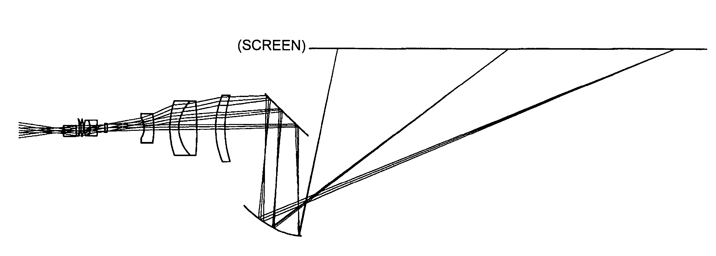
[0209]Embodiment 1 is a specific embodiment of the image projection apparatus and the projection optical system of FIGS. 7 and 8. That is, Embodiment 1 includes the first optical system 71 having positive power and including at least one dioptric system and the second optical system 72 including at least one reflecting surface having power and having positive power as a whole. The first and second optical systems 71 and 72 are arranged in the order described from upstream to downstream on the downstream side of the object surface. An object image is temporarily formed as an intermediate image, and thereafter, is formed as a final image. The optical elements 712 through 716, 721, and 722 are shifted or tilted with respect to the optical axis of the optical element 711 having refractive power, which is positioned at the furthest upstream end of the first optical system 71.

[0210]The magnification of the intermediate image is approximately 3×.

[0211]The data of Embodi...

embodiment 2

[0221][Embodiment 2]

[0222]Embodiment 2 is a specific embodiment of an image projection apparatus and a projection optical system shown in FIG. 12. In FIG. 12, the projection optical system of the image projection apparatus is shown enlarged.

[0223]The projection optical system includes a first optical system 81 and a second optical system 82. The first optical system 81 is composed of six lenses 811 through 816. The second optical system 82 is composed of two reflecting surfaces 821 and 822. A diaphragm (not graphically represented) is provided between the lenses 813 and 814.

[0224]Like in Embodiment 1, an intermediate image is formed as an inverted image by the first optical system 81 between the reflecting surfaces 821 and 822. The reflecting surface 821, which has positive power and reflects a light beam made incident on the second optical system 82 first, has a rotationally symmetric aspheric figure. The reflecting surface 822 is a polynomial free-form surface. In Embodiment 2, th...


PUM

PropertyMeasurementUnit
angleaaaaaaaaaa
distanceaaaaaaaaaa
distanceaaaaaaaaaa

Abstract

A projection optical system guiding and projecting a light beam from a projected object surface onto a projection surface in an upstream-downstream direction through a transmission dioptric system and a reflection dioptric system. An intermediate image surface of the projected object surface is positioned closer to the reflection dioptric system than to the transmission dioptric system, and an intermediate image on the intermediate image surface is formed as the final image on the projection surface via the reflecting mirrors, which include at least one anamorphic polynomial free-formed surface having different vertical and lateral powers. A light beam from the reflection dioptric system to the projection surface is guided at an angle to a normal of the projection surface and the transmission dioptric system is decentered with respect to a normal of the projected object surface, the transmission refractive elements prevented from being decentered with respect to each other.

Description

BACKGROUND OF THE INVENTION[0001]1. Field of the Invention[0002]The present invention relates to a projection optical system, a magnification projection optical system, a magnification projection apparatus, and an image projection apparatus.[0003]2. Description of the Related Art[0004]Liquid crystal projectors are widely known as image projection apparatuses. In these days, the liquid crystal projectors have employed liquid crystal panels with higher resolution, have enjoyed improved brightness due to higher efficiencies of light source lamps, and have become less expensive.[0005]Further, small, light-weight image projection apparatuses using a DMD (Digital Micromirror Device) have been widely used not only in offices and schools but also at home. Particularly, the portability of front-type projectors has been improved so that they are also used in small meetings.[0006]It is desired that projectors, or image projection apparatuses, be able to project a large-screen image. That is, i...

Claims


Application Information

Patent Timeline
Patent Type & Authority Patents(United States)
IPC IPC(8): G03B21/14G03B13/22G03B21/22G03B21/26G03B21/28G02B13/18G02B3/00G02B9/00G02B13/16G02B17/08G02F1/13
CPCG02B13/16G02B17/0852G02B17/0848G02B17/0816G03B21/28
Inventor TAKAURA, ATSUSHIFUJITA, KAZUHIROSAKUMA, NOBUO
Owner RICOH KK
Why Eureka
Try Eureka