
Axial flow turbine

a flow turbine and axial turbine technology, applied in the direction of machines/engines, stators, liquid fuel engines, etc., can solve the problems of increasing the loss of blade profiles, limiting the possibility of further improvement, and low speed

Inactive Publication Date: 2006-05-23
KK TOSHIBA
View PDF19 Cites 46 Cited by
  • Summary
  • Abstract
  • Description
  • Claims
  • Application Information

AI Technical Summary

Benefits of technology

[0037]In this aspect, the throat-pitch ratio “s / t”, which is increased from the minimized value to the blade-root portion, may be maximized at the blade-root portion.

Problems solved by technology

However, the flow velocity is low and the centrifugal force becomes small in the boundary zone in the passage between the blades, with the result that endurance against the pressure gradient from the front side “F” towards the back side “B” cannot be maintained, thus producing the secondary flow 8 of the working fluid, which is directed from the front side “F” toward the back side “B”.
Accordingly, there is a limitation for further improvement in performance, even when a larger amount of the main stream of the working fluid is supplied to flow.
It is known that, when the turbine nozzle unit and the turbine movable blade unit of the axial turbine generally have the small geometrical discharge angle or the large turning angle, the boundary zone develops on the surface of the blade, thus increasing the blade profile loss.

Method used


Image

  • Axial flow turbine
  • Axial flow turbine
  • Axial flow turbine

Examples


Embodiment Construction

[0054]Hereunder, embodiments of an axial turbine according to the present invention will be described with reference to the drawings. A steam turbine or a gas turbine is conceivable as the axial turbine described below, and an example thereof is schematically shown in FIG. 12.

[0055]More specifically, FIG. 12 shows the stages of the axial turbine 100 provided with nozzle diaphragms. Nozzle blades 104 are fixed to an outer diaphragm ring 102 and an inner diaphragm ring 103, which are secured in a turbine casing 101, to form nozzle blade passages. A plurality of turbine movable blades 106 is disposed on the downstream side of the respective blade passages. The movable blades 106 are implanted on the outer periphery of a rotor disc (wheel) 105 in a row at predetermined intervals. A cover 107 is attached on the outer peripheral edges of the movable blades 106 in order to prevent leakage of a working fluid in the movable blades.

[0056]In FIG. 12, the working fluid, i.e., steam “S” flows fr...


PUM


Abstract

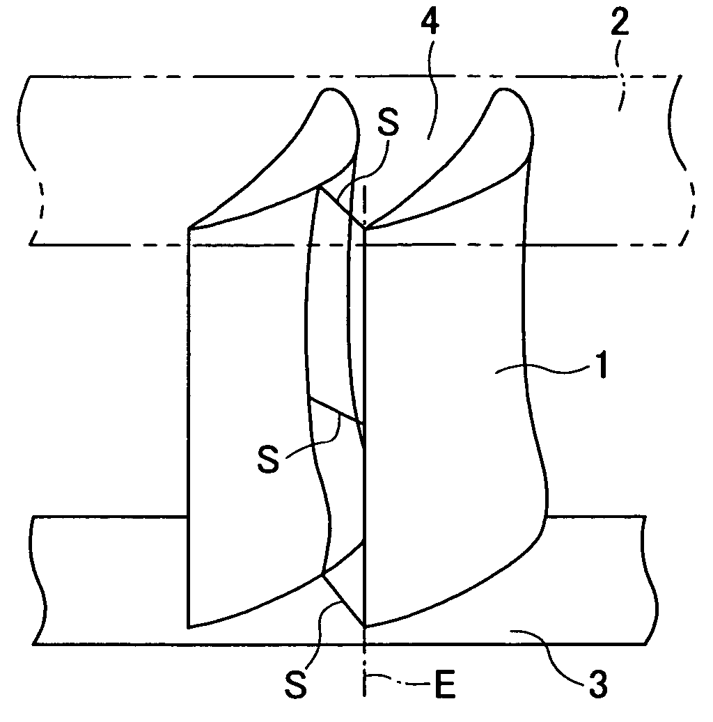
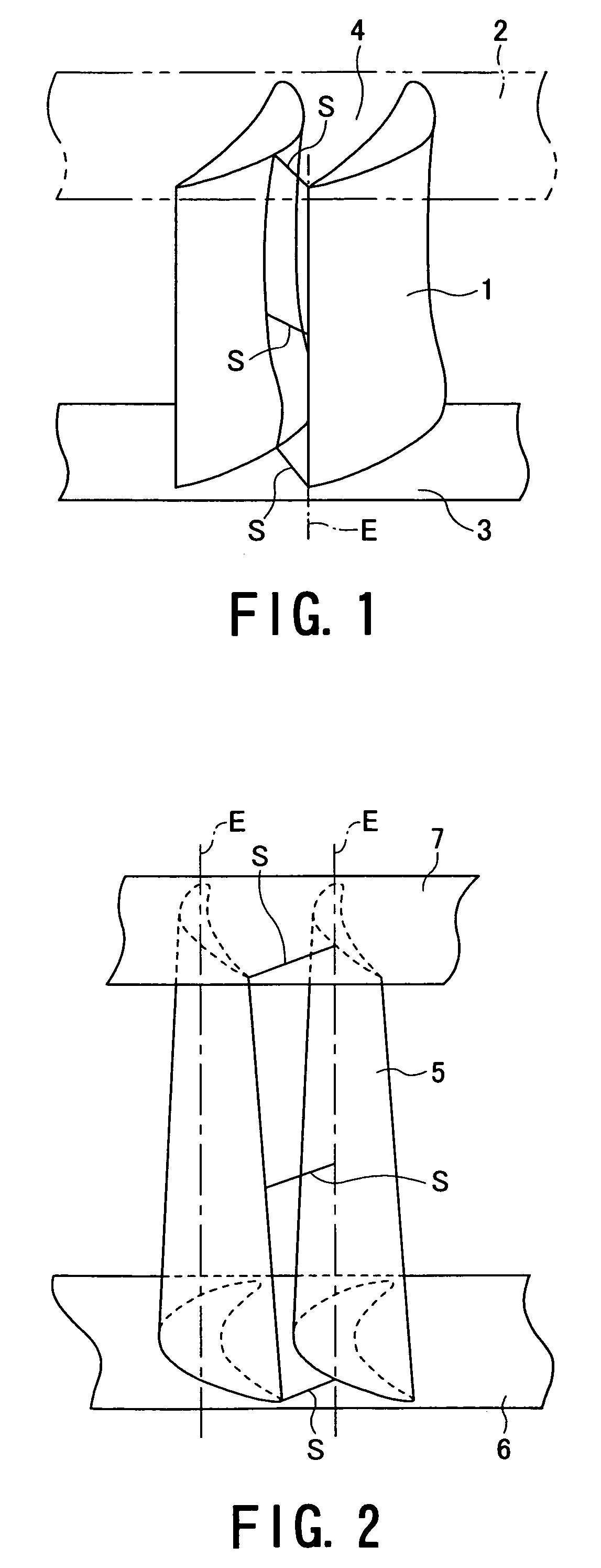
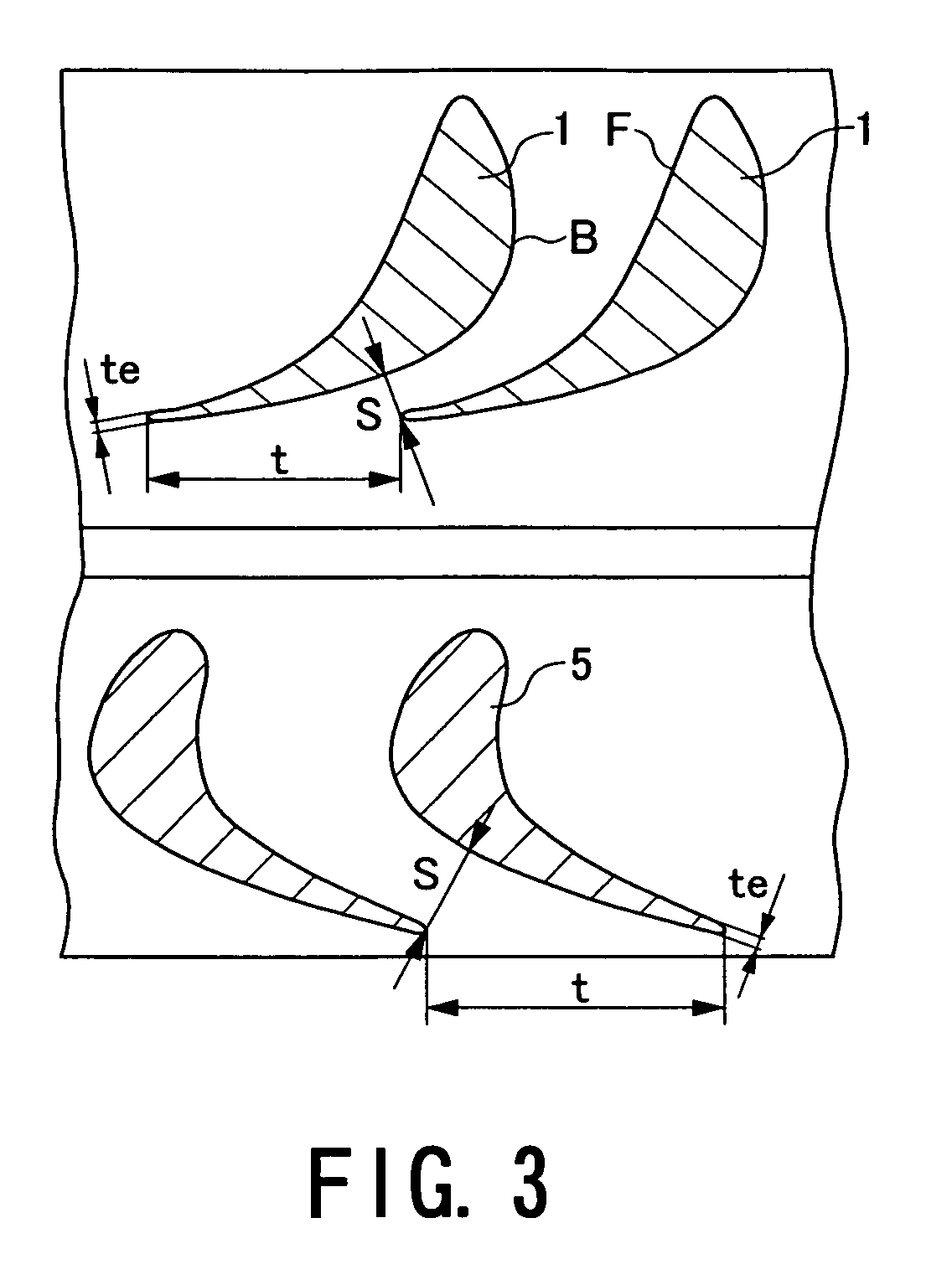
In the axial turbine according to the present invention, a nozzle blade 1 and / or a movable blade 5 has a profile in which a throat-pitch ratio “s / t” is maximized at a blade-central portion in height, wherein “s” being a shortest distance between a rear edge of a nozzle blade (movable blade) and a back side of another nozzle blade that is adjacent to the nozzle blade, and “t” being a pitch of the nozzle blades disposed in the row, minimized in a position between the blade-central portion in height and a blade-root portion and increased from a minimized value to the blade-root portion. This structure enables to provide the axial turbine, which permits to control flow distribution of the working fluid in the height direction of the blade in the passage between the blades of a turbine nozzle unit and a turbine movable nozzle and reduce the blade profile loss and the secondary flow loss at the blade-root portion, thus making a further improvement in the turbine stage efficiency.

Description

TECHNICAL FIELD[0001]The present invention relates to an axial turbine, especially to such an axial turbine, which has turbine stages formed by combining turbine nozzle units and turbine movable blade units together and permits to improve remarkably pressure efficiency of the turbine stages.BACKGROUND TECHNOLOGY[0002]In an axial turbine of a steam turbine or a gas turbine applied, for example, to a power plant, there have recently been reviewed improvement in thermal efficiency, and especially, improvement in a turbine internal efficiency, by which an economic operation can be carried out effectively.[0003]A subject to suppress the secondary flow loss due to the secondary flow of working fluid such as working steam or working gas in a turbine nozzle unit or a turbine movable blade unit, of losses including a blade profile loss occurring in a turbine blade and the secondary flow loss (secondary loss) of the working fluid, as low as possible, in order to improve remarkably the turbine...

Claims


Application Information

Patent Timeline
Patent Type & Authority Patents(United States)
IPC IPC(8): F01D5/14F01D9/02F01D9/04
CPCF01D5/14F01D5/143F01D9/041F01D9/02F01D5/145
Inventor TOMINAGA, JUNICHIKAWASAKI, SAKAETANUMA, TADASHIIMAI, KENICHI
Owner KK TOSHIBA
Learn More